4
* If the output shaft does not move, stop
voltage application. If voltage continues to
be applied, excessive heat will occur in
the starter solenoid and give thermal
damage to the coil, thereby making it
unserviceable.
Inspect that the current and revolution speed
satisfy the following standards when the
start switch is closed.
Voltage Current Speed
23.5 V 125 A max. 3000 rpm min.
It is not necessary to adjust the voltage to
the exact value of 23.5 V. If the voltage is
slightly higher, the rpm will be
proportionately higher, while if the voltage is
lower, the rpm will be proportionately lower.
The current is independent of the voltage,
and can be judged using the above
standard.
* Note that the starter solenoid will not
operate unless the voltage between the S-
terminal and the ground exceeds 16 V.
Test result and possible cause
1. Rated current draw and revolution speed
indicate normal condition of the starter.
2. Low revolution speed and high current
draw indicate:
a. Too much friction inside starter motor
such as clogging, dirt, wearing, faulty
bearings
b. Shorted circuit inside starter
3. No revolution of the output shaft indicates:
a. Grounded M-lead wire or field coils
b. Frozen bearings
4. No current draw indicates:
a. Open field coils
b. Open armature coils
c. Broken brush springs, worn brushes, or
high insulation resistance between
brushes and commutator
5. Extremely low revolution speed and low
current draw indicate:
Poor connection between M-terminal
and lead wire, or between bracket and
brush holder screws (body-ground type
only), damaged M-lead wire, damaged
brush pig tails, or poor contact between
commutator and brushes
6. High revolution speed and high current
draw indicate:
Shorted field coils
* In case of symptoms 2 to 6, replace the
starter, because of the possible failures
mentioned above.
2.5.3 Output shaft play
Before reinstalling the starter to the engine,
follow the procedure below to inspect the
output shaft clearance.
1. Remove the M-terminal nut and keep the
lead wire end in contact with the M-
terminal.
2. Apply voltage to between the S-terminal
and the ground to let the pinion advance
forward. Immediately after that, separate
the lead wire from the M-terminal. The
pinion stays in the advanced forward
position until the battery is disconnected.
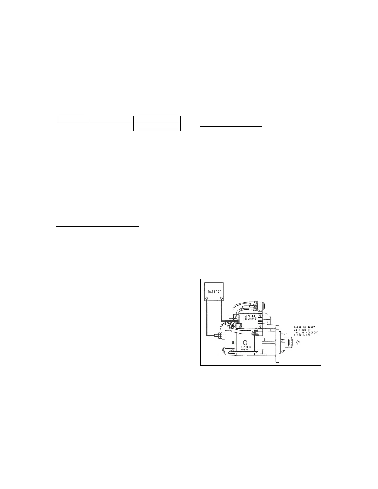
3. As described in figure 8, measure the
distance between the shaft pressed-in
and pulled-out positions. The play should
be within 0.004" to 0.118" (0.1 to 3.0
mm). If the measured value does not
satisfy the standard, replace the starter.
Figure 8 - CHECKING OUTPUT SHAFT CLEARANCE
(GROUND-FLOAT TYPE)