Section 3
Compressor Replacement
Copyright 2002 Maintenance Manual MM-0204
Page 12 ArvinMeritor, Inc. Issued 08-02
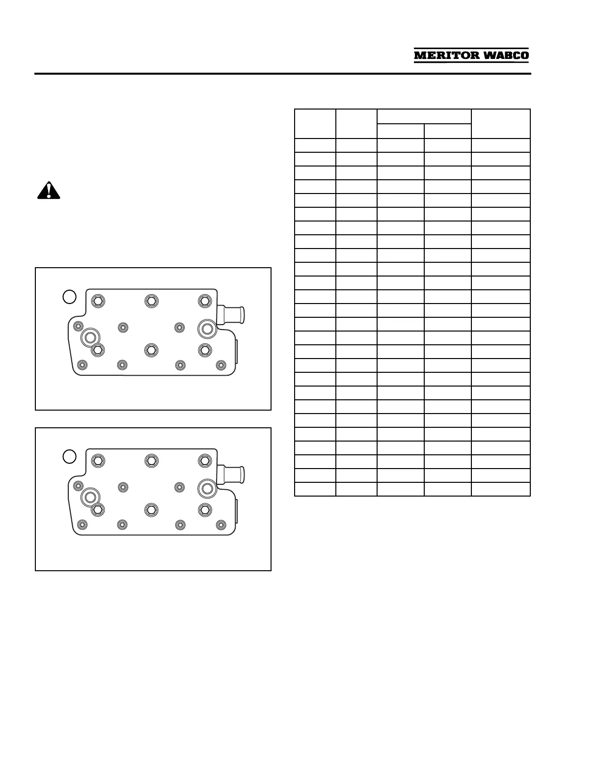
5. Install the six hex head mounting bolts that
hold the cylinder head in place. Tighten the
mounting bolts in sequence per Table B,
following Steps 1-12.
Figure 3.7
.
6. Use a Torx
®
tool to tighten the seven Torx
®
head screws in sequence per Table B,
following Steps 13-26.
Figure 3.8
.
CAUTION
Use the proper tools to perform this torque-turn
bolt tightening sequence exactly as shown in
Table B. Accuracy is CRITICAL to your field service
success!
Table B: Bolt Tightening Sequence
7. Follow the steps listed in Compressor
Installation to reinstall the compressor and
test for leaks.
Figure 3.7
1 Tighten bolts in sequence shown.
Figure 3.8
1 Tighten bolts in sequence shown.
4000274b
1
AE
B
F
C
D
4000275b
1
I
K
J
HG
LM
Step Bolt
Torque
Rotation
(Degrees) (N•m) lb-ft
1 A 25
+0
-5
18.5
+0
-3.7
2 B 25
+0
-5
18.5
+0
-3.7
3 C 25
+0
-5
18.5
+0
-3.7
4 D 25
+0
-5
18.5
+0
-3.7
5 E 25
+0
-5
18.5
+0
-3.7
6 F 25
+0
-5
18.5
+0
-3.7
7 A 150°
+15
-5
8 B 150°
+15
-5
9 C 120°
+15
-5
10 D 120°
+15
-5
11 E 120°
+15
-5
12 F 120°
+15
-5
13 G 6
+6
-6
4.4
+4.4
-4.4
14 H 6
+6
-6
4.4
+4.4
-4.4
15 I 6
+6
-6
4.4
+4.4
-4.4
16 J 6
+6
-6
4.4
+4.4
-4.4
17 K 6
+6
-6
4.4
+4.4
-4.4
18 L 6
+6
-6
4.4
+4.4
-4.4
19 M 6
+6
-6
4.4
+4.4
-4.4
20 G 135°
+15
-5
21 H 135°
+15
-5
22 I 135°
+15
-5
23 J 135°
+15
-5
24 K 135°
+15
-5
25 L 135°
+15
-5
26 M 135°
+15
-5