3 Diagnostics, Troubleshooting and Testing
30
Meritor WABCO Maintenance Manual MM-0112 (Revised 07-05)
Location of Sensors
On steering axles, the sensor is accessible on the in-board side of
the steering knuckle.
On drive axles, the drum assembly may have to be pulled to gain
access to the sensor.
Sensor Adjustment
앫 Push the sensor in until it contacts the tooth wheel.
앫 Do not pry or push sensors with sharp objects.
앫 Sensors will self-adjust during wheel rotation.
Sensor Output Voltage Test
Voltage must be at least 0.2 volts AC at 30 rpm.
1. Turn ignition OFF.
2. Disconnect the appropriate connector from the ECU (refer to
Appendix II).
3. Rotate the wheel by hand at 30 rpm (1/2 revolution per
second).
4. Measure the voltage at the pins indicated in Table G.
앫 If the minimum output voltage is less than 0.2: Push the
corresponding sensor toward the tooth wheel, then repeat
the measurement.
Table G: Sensor Check Pins
Sensor Resistance
The sensor circuit resistance must be between 900 and
2000 ohms. Resistance can be measured at the sensor connector,
or at the pins on the ECU connector. To measure resistance:
1. Turn ignition OFF.
2. To measure resistance at the sensor connector, disconnect the
ECU connector from the ECU. To measure resistance at the
sensor connector, disconnect the sensor from the sensor
extension cable.
3. Measure output at the pins indicated in Table G.
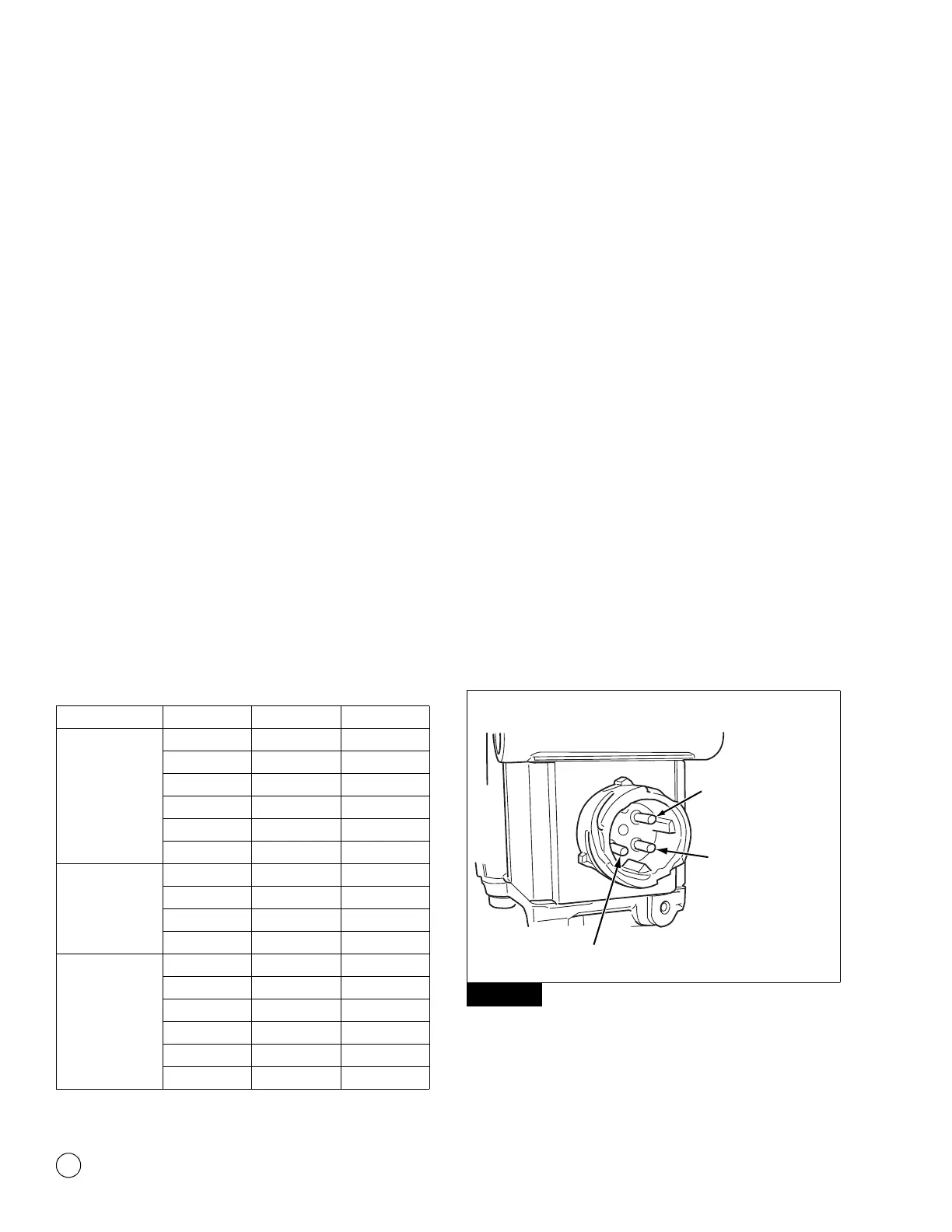
Valve Tests
ABS Modulator Valve
Measure resistance across each valve solenoid coil terminal and
ground on the ABS valve to ensure 4.0 to 9.0 ohms. Figure 3.25
and Figure 3.26.
앫 If the resistance is greater than 9.0 ohms, clean the electrical
contacts in the solenoid. Check the resistance again.
앫 To check the cable and the ABS valve as one unit, measure
resistance across the pins on the ECU connector of the harness.
Check the diagram of the system you are testing for pin
numbers. (Refer to Appendix II.)
Figure 3.25
ECU Sensor Connector Pins
Universal LF 18-Pin 12 and 15
RF 18-Pin 10 and 13
LR 18-Pin 11 and 14
RR 18-Pin 17 and 18
6S/6M LR (3rd Axle) 15-Pin 2 and 5
6S/6M RR (3rd Axle) 15-Pin 11 and 14
Basic LF 18-Pin 12 and 15
RF 18-Pin 10 and 13
LR 18-Pin 11 and 14
RR 18-Pin 17 and 18
Frame-mounted LF X2 — Black 7 and 8
RF X2 — Black 5 and 6
LR X3 — Green 1 and 2
RR X3 — Green 3 and 4
LR (3rd Axle) X4 — Brown 3 and 4
RR (3rd Axle) X4 — Brown 5 and 6
Figure 3.25
BAYONET-STYLE CONNECTOR
4004022a
EXHAUST SOLENOID
(BLUE WIRE)
INLET SOLENOID
(BROWN WIRE)
GROUND TERMINAL