4 Component Replacement
35
Meritor WABCO Maintenance Manual MM-0112 (Revised 07-05)
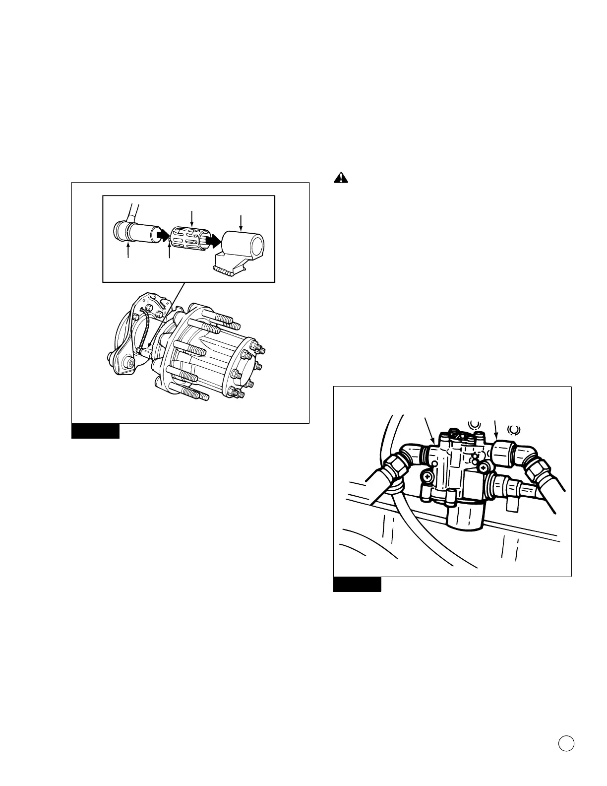
NOTE: After installation, there should be no gap between the
sensor and the tooth wheel. During normal operation, a gap of
up to 0.04-inch (1.016 mm) is allowable.
4. Push the sensor completely into the sensor spring clip until it
contacts the tooth wheel. Figure 4.3.
Figure 4.3
5. Insert the sensor cable through the hole in the spider and axle
housing flange. Route the cable to the frame rail. Be sure to
route the cable in a way that will prevent pinching or chafing
and will allow sufficient movement for suspension travel.
6. Connect the sensor cable to the chassis harness.
7. Install the fasteners that hold the sensor cable in place.
8. Install the brake drum on the wheel hub.
9. Complete the installation per the vehicle manufacturer’s
manual.
ABS Modulator Valve
Removal
1. Turn the ignition switch to the OFF position. Apply the parking
brake.
WARNING
Park the vehicle on a level surface. Block the wheels to
prevent the vehicle from moving. Support the vehicle with
safety stands. Do not work under a vehicle supported only by
jacks. Jacks can slip and fall over. Serious personal injury and
damage to components can result.
2. Place blocks under the front and rear tires to stop the vehicle
from moving.
3. If necessary, raise the vehicle off the ground and place safety
stands under the axle.
4. Disconnect the wiring connector from the ABS valve.
5. Disconnect the air lines from Ports 1 (air supply) and 2 (air
discharge) of the ABS valve. Figure 4.4.
Figure 4.4
6. Remove the two mounting capscrews and nuts.
7. Remove the ABS valve.
Figure 4.3
1002037a
SENSOR
HOLDER
SPRING CLIP
SPRING
CLIP TAB
SENSOR
Figure 4.4
1002038a
PORT 1,
AIR IN
PORT 2,
AIR OUT
 Loading...