4 Component Replacement
36
Meritor WABCO Maintenance Manual MM-0112 (Revised 07-05)
Installation
CAUTION
Moisture can affect the performance of all ABS/ATC systems,
as well as the standard braking system. Moisture in air lines
can cause air lines to freeze in cold weather.
1. Install the ABS valve with two mounting capscrews and nuts.
Tighten the capscrews per the manufacturer’s
recommendation.
2. Connect the line to the brake chambers to Port 2 of the ABS
valve. Connect the air supply line to Port 1 of the ABS valve.
3. Connect the wiring connector to the ABS valve. Hand tighten
only.
4. Remove the blocks and stands.
5. Test the installation.
Checking the Installation
1. Apply the brakes. Listen for leaks at the modulator valve.
2. Turn the ignition on and listen to the modulator valve cycle. If
the valve fails to cycle, check the electrical cable connection.
Make repairs as needed.
3. Drive the vehicle. Verify that the ABS indicator lamp operates
correctly.
ATC Valve
Removal
1. Turn the ignition switch to the OFF position. Apply the parking
brake.
WARNING
Park the vehicle on a level surface. Block the wheels to
prevent the vehicle from moving. Support the vehicle with
safety stands. Do not work under a vehicle supported only by
jacks. Jacks can slip and fall over. Serious personal injury and
damage to components can result.
2. Place blocks under the front and rear tires to stop the vehicle
from moving.
3. If necessary, raise the vehicle off the ground. Place safety
stands under the axle.
4. Relieve line pressure by bleeding the air from the
appropriate supply tank.
5. Disconnect the wiring from the ATC valve.
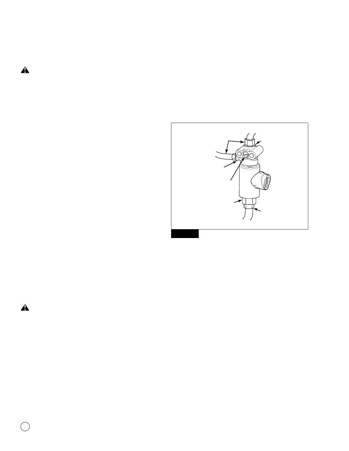
6. Disconnect the air lines from Port 1 (air supply), Port 2 (air
discharge) and Port 3 (treadle) of the ATC valve. Figure 4.5.
Figure 4.5
7. Remove the two mounting capscrews and nuts. Remove the
ATC valve.
Installation
1. Install the ATC valve with two mounting capscrews and nuts.
Tighten the capscrews per the manufacturer’s
recommendation.
2. Connect the air supply, discharge and treadle lines to Ports 1,
2 and 3 of the ATC valve.
3. Connect the harness connector to the ATC valve. Hand tighten
only.
4. Remove the blocks and stands.
5. Test the installation.
Figure 4.5
1002039a
AIR
LINES
PORT 1,
AIR SUPPLY
AIR LINE
PORT 3,
TREADLE
VALVE CONTROL
DO NOT OPEN
PORT 2,
AIR DISCHARGE