Section 16: SUSPENSION
PA1562
8
2.2.3 Installation
1. Ensure that the shock absorber mounting
pins are tight and that the threads are not
stripped.
2. Install new rubber mounting bushings on
shock absorbers (upper and lower).
3. Place the inner washers (with washer
convex side facing the shock absorber
rubber bushing) on each shock absorber pin
(Fig. 5).
4. Install the shock absorber eyes over the
mounting pins, then the outer washers (with
washer convex side facing the shock
absorber rubber bushing) on each shock
extremity.
NOTE
If shock absorber pins are removed, they must
be reinstalled using “loctite” (see “Parts
Specifications” in this section).
FIGURE 5: TYPICAL SHOCK ABSORBER SETUP
16009
5. Place the lower and upper mounting pin
stud nuts and torque to 70 - 80 lbf-ft (95 –
110 Nm).
2.3 RADIUS RODS
Radius rods are used to secure the axles in the
proper transversal and longitudinal positions.
Four radius rods are provided on the front axle
suspension (three longitudinal and one
transversal). Refer to figures 1, 2 and 6 for
details. These rods transmit both braking and
driving forces from the axles to the vehicle body.
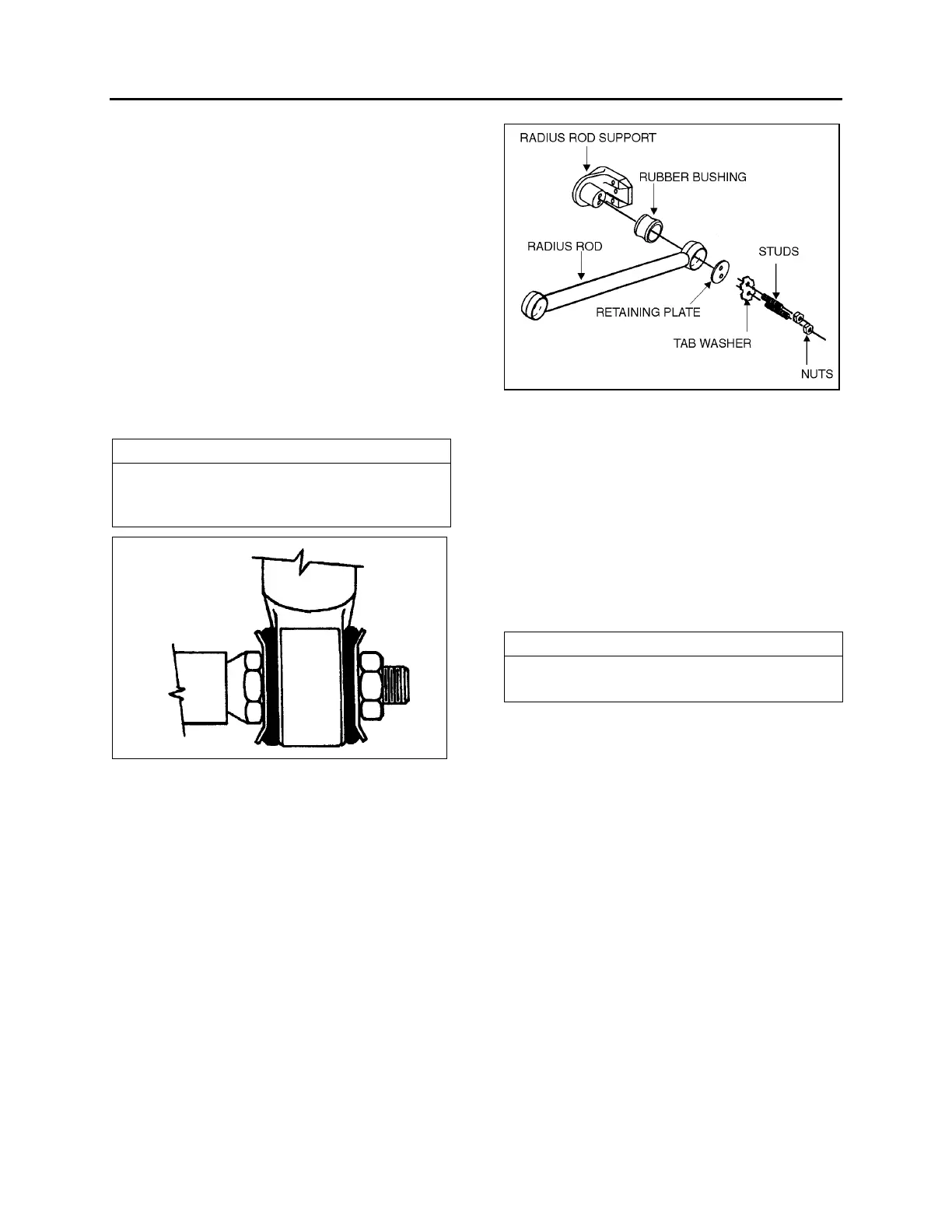
FIGURE 6: TYPICAL RADIUS ROD SETUP 16010
2.3.1 Inspection
The following instructions apply to all radius rods
used on this vehicle:
1. Clean all parts thoroughly.
2. Inspect radius rods for distortion and cracks.
We recommend the “Magnaflux” process to
detect cracks in the radius rod. Any
damaged part should be replaced with a
new one.
NOTE
New bushings should be used when rods are
replaced.
3. The radius rod bushings should be checked
periodically for signs of shearing,
deterioration, or damage. Any defective part
should be replaced with a new one.
2.3.2 Removal
1. Flatten the tab washer which secures the
two retaining nuts (or bolts), then unscrew
the nuts (or bolts) at each extremity of the
radius rod (Fig. 6).
2. Remove the tab washer and the retaining
plates and radius rod ends from anchor
pins, and then remove the radius rod.
2.3.3 Bushing removal
1. Safely support the radius rod as shown in
figure 7.