Section 16 : SUSPENSION
PA1562
16
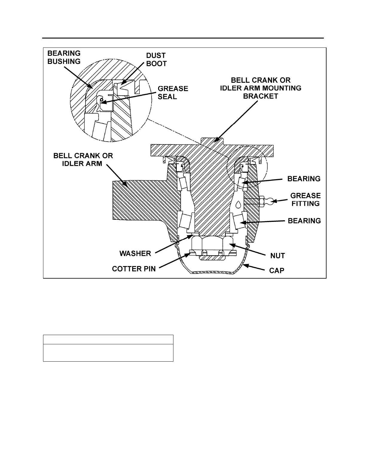
FIGURE 21: BELL CRANK AND IDLER ARM BALL JOINT 16109
3.8 RELAY ROD
Relay rod ends are equipped with lubrication
fittings and should be lubricated as directed in
paragraph "3.11 Lubrication Fittings" in this
section.
NOTE
The relay rod is crimped in place and it is not
possible to remove the ball joints.
3.8.1 Replacement
1. Remove cotter pins from bell crank and idler
arm end of relay rod. Loosen nuts flush with
end of studs.
2. Use a puller or place a sledge hammer
behind the adjacent part to absorb shocks.
Strike the studs with a brass hammer to
loosen end assemblies.
3. Remove stud nuts and washers then
remove studs.
4. Position relay rod studs into bell crank and
idler arm then tap stud ends with a brass
hammer to seat tapered surfaces.
5. Install washers and stud nuts. Tighten nuts
to 160 lbf-ft (220 Nm) torque. Align cotter pin
slot (tighten) and install a new cotter pin.
3.9 TIE RODS
Tie rod ends are connected to the bell crank and
left steering arm, and to the idler arm and right
steering arm. Each tie rod assembly consists of
three parts; a tube and two socket end
assemblies. The tie rod ends are threaded into
the tube and secured with clamp bolts. Right
and left hand threads are provided to ease toe-
in adjustment. Tie rod assemblies are inter-
changeable from the right to the left side of the
coach.