Section 16: SUSPENSION
PA1562
15
Bell crank: Disconnect drag link, tie rod and
relay rod from bell crank by removing cotter
pins, stud nuts and washers from ball studs.
Separate socket assemblies from the bell crank.
Idler arm: Remove cotter pins, nuts and
washers from ball studs connecting relay rod
and tie rod to idler arm. Separate socket
assemblies from idler arm.
Remove nuts and washers from bolt attaching
bell crank or idler arm mounting bracket to
vehicle understructure. Remove bell crank or
idler arm mounting bracket.
3.7.2 Bell crank or Idler Arm Ball Joint
Disassembly
1. Remove adjacent link assemblies from bell
crank or idler arm as previously described.
2. Remove the cap (Fig.21).
3. Remove the cotter pin, nut and tongue
washer. Remove bearings, grease seal,
bearing bushing and the bell crank or idler
arm from its mounting bracket stud (Fig. 21).
3.7.3 Bell Crank or Idler Arm Ball Joint
Reassembly
NOTE
For bearing installation use tool Prévost #
110684.
1. Install bearing bushing on bell crank or idler
arm mounting bracket stud.
2. Install bearing and grease seal in bell crank
or idler arm eye (Fig. 21).
NOTE
Install grease seal according to figure 21.
Grease must be able to exit the bell crank or
idler arm mechanism. For grease seal
installation use tool Prévost # 110683.
3. Install bell crank or idler arm on its mounting
bracket stud (Fig. 21).
4. Install bearing and nut.
NOTE
Apply grease on bearing before installation.
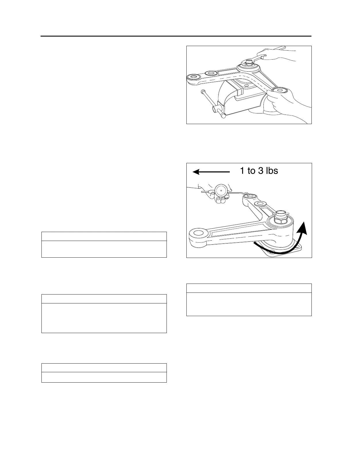
5. Firmly tighten nut (Fig. 19).
6. Unscrew nut until bell crank or idler arm
starts to turn by the application of 1 to 3
pounds load (Fig. 20).
FIGURE 19: BELL CRANK 16044
7. Check for loose bearings by applying an up
and down load on bell crank or idler lever
(Fig. 20). The lever is not supposed to move
in the vertical axis direction.
FIGURE 20: BELL CRANK 16045
8. Align nut with cotter pin slot (tighten) and
install a new cotter pin.
NOTE
Bend cotter pin around the nut (Fig. 21). Do
not bend the cotter pin in the direction of the
cap, because it may interfere with the cap.
9. Install the cap.
10. Bell crank: Install drag link, tie rod and
relay rod as directed herein under each
specific subject.
11. Idler arm: Install tie rod and relay rod as
directed herein under each specific subject.
12. Adjust turning angle as previously directed
under paragraph "Turning Angle" and
check front end alignment as specified in
paragraph "3.16. Front End Alignment" of
this section.