Section 16 : SUSPENSION
PA1562
14
4. Check the radial position of the pitman arm
in relation to the sector shaft prior to
removal of pitman arm.
5. Add reference marks to the arm and shaft if
necessary to ensure correct alignment at
reassembly.
6. Use a puller to remove pitman arm.
3.5 PITMAN ARM INSTALLATION
1. Position pitman arm on sector gear shaft
with reference marks aligned.
2. Install fixing nut. Tighten nut to 400-450 lbf-ft
(545-610 Nm).
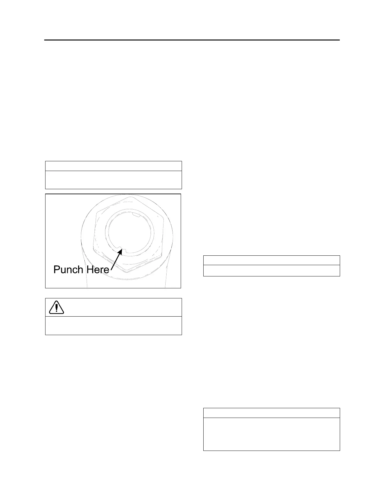
NOTE
Use a new nut if the previously removed nut
was punched.
FIGURE 18: FIXING NUT PUNCH MARK
16098
CAUTION
Lock nut with sector shaft using a punch mark
into the groove (Refer to figure 18).
3. Connect drag link to pitman arm. Install
washers. Tighten nut to 160-215 lbf-ft (220-
290 Nm). Advance nut to next alignment
cotter pin slot and install a new cotter pin.
3.6 DRAG LINK
Drag link assembly consists of three parts; a
drag link and two end assemblies. Both end
assemblies are identical and they are retained
on the drag link with a clamp bolt and nut.
Stud nuts at the pitman arm and bell crank ends
of the drag link must be kept tight or hole at ball
stud end of drag link and hole in pitman arm
may become enlarged as a result of excessive
looseness. Subsequent tightening of stud nuts
may draw studs too far into holes and dust cover
parts may become damaged which can result in
component failure.
Drag link end sockets are equipped with
lubrication fittings and should be lubricated as
directed in "Lubrication Fittings" in this section.
3.6.1 Adjustment
It should not be necessary to alter the length of
the drag link except when a new link is installed
or when removable end assembly has been
replaced. If drag link adjustment is necessary,
proceed as follows:
1. Position front wheels in straight ahead
position.
2. Center steering gear as previously
explained in paragraph "3.3 Steering
Linkage Adjustment".
3. Remove cotter pin and stud from drag link at
bell crank. Locate centerline of vehicle and
center of relay rod. With center of relay rod
aligned with centerline of vehicle, loosen
clamp bolt at socket end (bell crank end) of
drag link and adjust length of socket end
assembly to fit in boss of bell crank.
NOTE
Do not change position of pitman arm.
4. Install stud nut and torque to 160 lbf-ft (220
Nm). Align nut with cotter pin slot (tighten)
and install a new cotter pin.
5. Torque mounting clamp bolt nut to 40-60 lbf-
ft (55-80 Nm), then test the adjustment.
Front wheels should turn from right to left
extremities without noticeable binding at
drag link ends.
3.7 BELL CRANK AND IDLER ARM
Bell crank and idler arm are equipped with one
lubrication fitting and should be lubricated as
directed in paragraph "3.11 Lubrication Fittings"
of this Section.
3.7.1 Bell Crank and Idler Arm Removal
NOTE
Use a piece of wire to anchor loosen end of
relay rod and tie rod in order to prevent
placing an excessive load on opposite socket
end.