Section 16: SUSPENSION
PA1562
13
FIGURE 15: CLAMP POSITIONING 16171
FIGURE 16: CLAMP POSITIONING 16172
3.2 POWER STEERING HYDRAULIC PUMP
Refer to the "TRW Power Steering Pump
Service Manual" annexed at the end of Section
14.
3.3 STEERING LINKAGE ADJUSTMENT
NOTE
Whenever a steering linkage component has
been removed and replaced, check steering
geometry and front end alignment as directed
in this Sectiont. Check to insure that all stud
nuts and mounting bolts and nuts have been
tightened to proper torques listed under "14.
Torque Specifications" at the end of this
section.
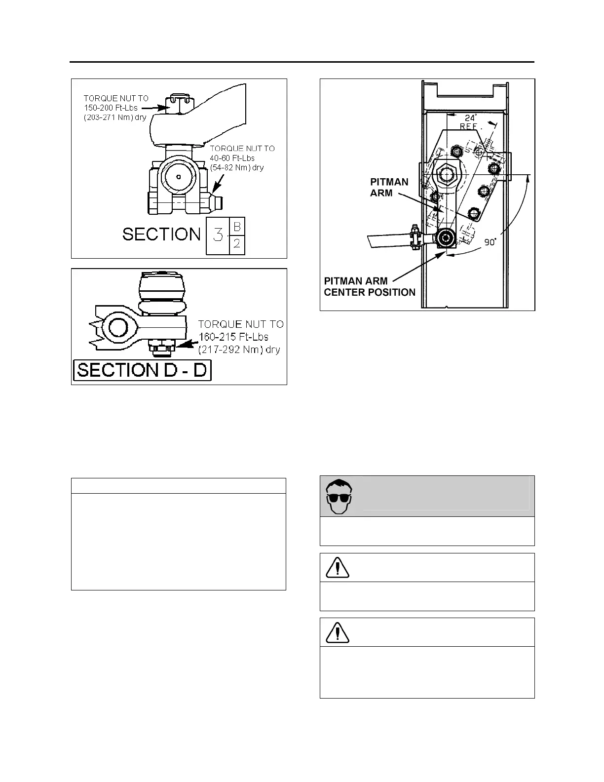
1. First, align input shaft marks.
2. Afterwards, the pitman arm should be
adjusted with reference mark aligned or to
an angle of 90° in relation with the horizontal
axis (Fig. 17).
3. Locate centerline of vehicle then install relay
rod in boss at steering bell crank and idler
arm. Align center of relay rod with centerline
of vehicle.
FIGURE 17: PITMAN ARM ALIGNMENT 14057
4. Install drag link to pitman arm and adjust
opposite end of drag link to fit mounting stud
hole in bell crank.
5. Install tie rods, and then adjust toe-in as per
"Front End Alignment" in this Section.
3.4 PITMAN ARM REMOVAL
1. Remove cotter pin, nut and washer from
drag link ball stud at pitman arm.
2. Disconnect drag link from pitman arm, using
jaw style pullers (pressure screw type).
WARNING
Always wear approved eye protection when
operating pullers.
CAUTION
Do not drive pitman arm on or off pitman shaft
as this can damage the steering gear.
CAUTION
Heating of components to aid in disassembly
is not allowed because it has a detrimental
effect on axle components and steering
linkages.
3. Remove pitman arm fixing nut.