Chapter 7 Gated Operation with a PTG 101
PTG as Master Clock
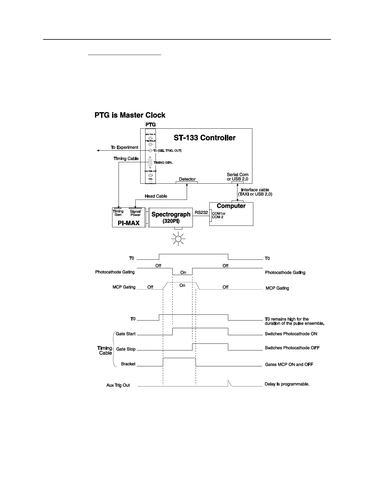
If you have a light source that has a "Trigger In", the PTG can be used as the Master
clock (cable connections shown in Figure 53). The setup procedure is much the same as
that given for the "Experiment as Master Clock". The differences are that a cable is
connected between the PTG's T0 BNC and the light source (experiment) for triggering
the event and that the 25 ns propagation delay for the External Trigger is no longer a
factor.
Figure 53. PTG is Master Clock: Hardware Setup and Timing Diagram