153
Chapter 14
System Component Descriptions
Introduction
PI-MAX is an advanced intensified CCD (ICCD) camera system used for low light and
time resolved applications. It consists of an imaging (square) or spectroscopy
(rectangular) format CCD coupled to Generation II (PI-MAX RB, SB, UV) or Generation
III (PI-MAX HQ) intensifiers. The operation of the camera system is under complete
control of WinView/32 (Imaging) or WinSpec/32 (Imaging and Spectroscopy) software
packages. In pulsed/gated experiments, where the camera needs to be synchronized to a
light source such as laser, an integrated Programmable Timing Generator™ (PTG) or an
external delay generator (e.g., DG535 from Stanford Research Systems) is used.
PI-MAX Camera
Mount Adapters
The nose at the front end of the PI-MAX camera is designed to accept three types of
mount adapters: C-mount, F-mount, and Spectroscopy-mount. The PI-MAX is supplied
with the mount adapter specified when the system was ordered. For more information about
these mount adapters, refer to Appendix D for C- and F-mount adapters and refer to
Appendix E for spectroscopy-mount adapters and spectrograph adapters.
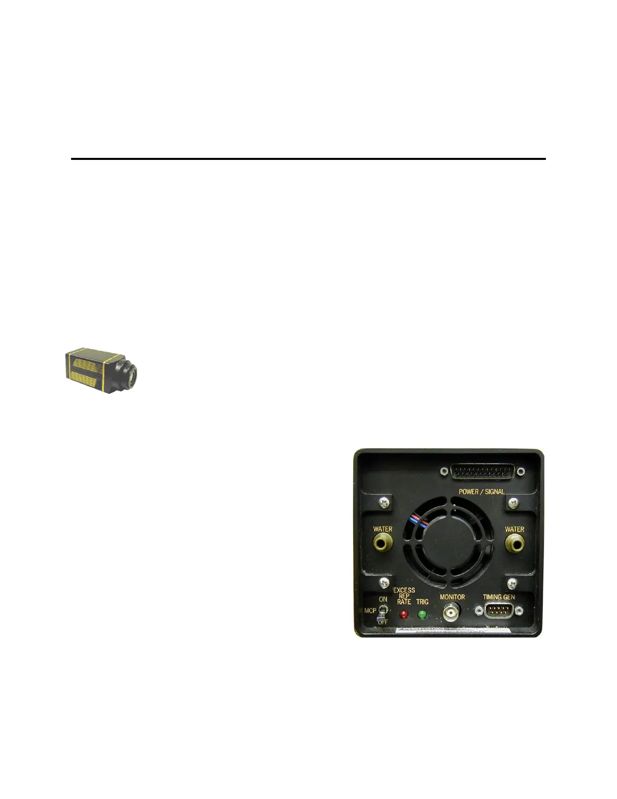
Switches, Connectors and Indicators
Power/Signal connector: (standard
PI-MAX) 25-pin D connector; connects
to Controller cable (6050-0336); other
end of cable connects to Detector
connector of ST-133 Controller. See
Figure 88.
Signal connector: (PI-MAX2) 40-pin
connector; connects to Signal cable (6050-
0492); other end of cable connects to
Signal connector of ST-133 Controller.
See Figure 89.
Power connector: (PI-MAX2) 15-pin D
connector; connects to Power cable
(6050-0493); other end of cable connects
to Camera Pwr connector of ST-133
Controller. See Figure 89.
Timing Gen connector: 9-pin D
connector; allows connections between
PI-MAX and the Timing Generator
(PTG or Stanford Research DG535).
Figure 88. PI-MAX Rear Panel