Chapter 8 Gated Operation with a DG535 119
the data, it is essential that the timing generator be inhibited during each readout. This is
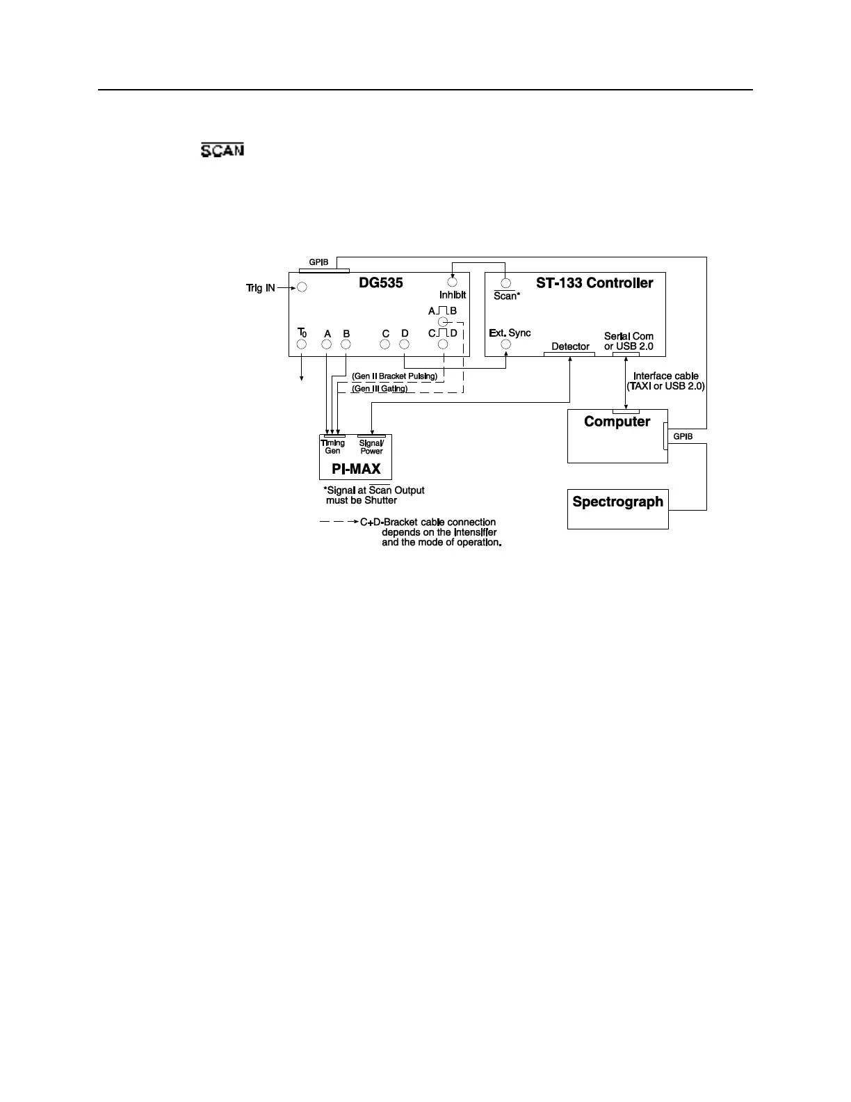
accomplished by connecting the controller’s Shutter output signal (provided at ST-133’s
output) to the Inhibit input of the DG535. The DG535 parameters are set from
the computer by the application software.
Other system cabling would include the Detector-Controller cable that interconnects the
PI-MAX and the controller, the TAXI cable between the controller and the computer, and
the GPIB link between the computer and the DG535.
Figure 73. MCP Gated Operation Cabling
Figure 74 is a timing diagram for a DG535. A diagram of the PTG timing would be
similar, the principal difference being that the insertion delay would be 25 ns instead of
the 85 ns insertion delay characteristic to the DG535.