Chapter 14 System Component Descriptions 159
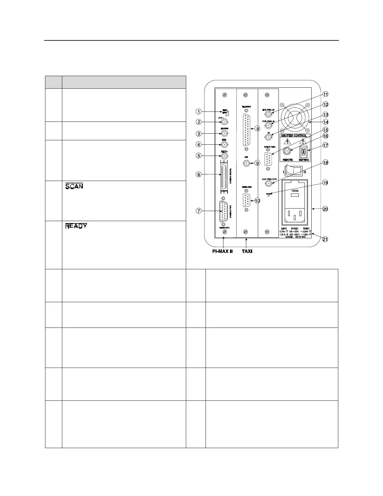
PI-MAX2 Controller Rear Panel Features: The descriptions of the rear panel connectors are keyed to
the accompanying figure. The TAXI Interface Control Module is installed in the second from the left slot (as
you face the rear of the ST-133). The Fuse/Voltage label will be above or below the Power Module.
Figure 92. ST-133 (PI-MAX2) Rear Panel Callouts
Temperature Lock LED: Indicates that the
temperature control loop has locked and that
the temperature of the CCD array will be
stable to within 0.05C.
Aux Output: This output is reserved for
future use.
External Sync Input: TTL input that has a
10 k pullup resistor. Allows data acquisition
and readout to be synchronized with external
events. Through software, positive or negative
(default) triggering can be selected.
Output: WinView/32 (ver. 2.4 and
higher) software selectable NOT SCAN or
SHUTTER signal. Default is SHUTTER.
Output: Initially HIGH. Changes state
on completion of cleaning cycles before the first
exposure.
Camera Signal Connector: Transmits control
information to the camera and receives data
back from the camera via the Signal cable
(6050-0492).
Fan: Cools the controller electronics. Runs
continuously when the controller is turned on.
Camera Power Connector: Transmits power
to the camera from the Controller via the
Power cable (6050-0493).
Timing Gen.: Gate Start/Stop and Bracket signals
are provided at this connector. This output must be
cabled to the PI-MAX2 Timing Gen connector.
TTL In/Out: User-programmable interface with
eight input bits and eight output bits that can be
written to or polled for additional control or
functionality. Output is not currently supported
under USB 2.0. See Chapter 13.
Remote Shutter Connector: Unless the PI-MAX2
system is powering a slit shutter for a spectrograph,
this connector can be ignored.
AUX Output: Reserved for future use.
Shutter Setting Selector: Sets the shutter hold
voltage. Unless the PI-MAX2 system is powering
a slit shutter for a spectrograph, this functionality
can be ignored.
Serial COM Connector: Provides two-way
serial communication between the controller and
the host computer.
Aux. Trig. Out: AC-coupled variable delay trigger
output for synchronizing other system components
with PTG. The host software sets the Delay Time of
this output with respect to the PTG trigger time. This
output does not need to be connected to the
PI-MAX2.