Chapter 9 Kinetics Operation 127
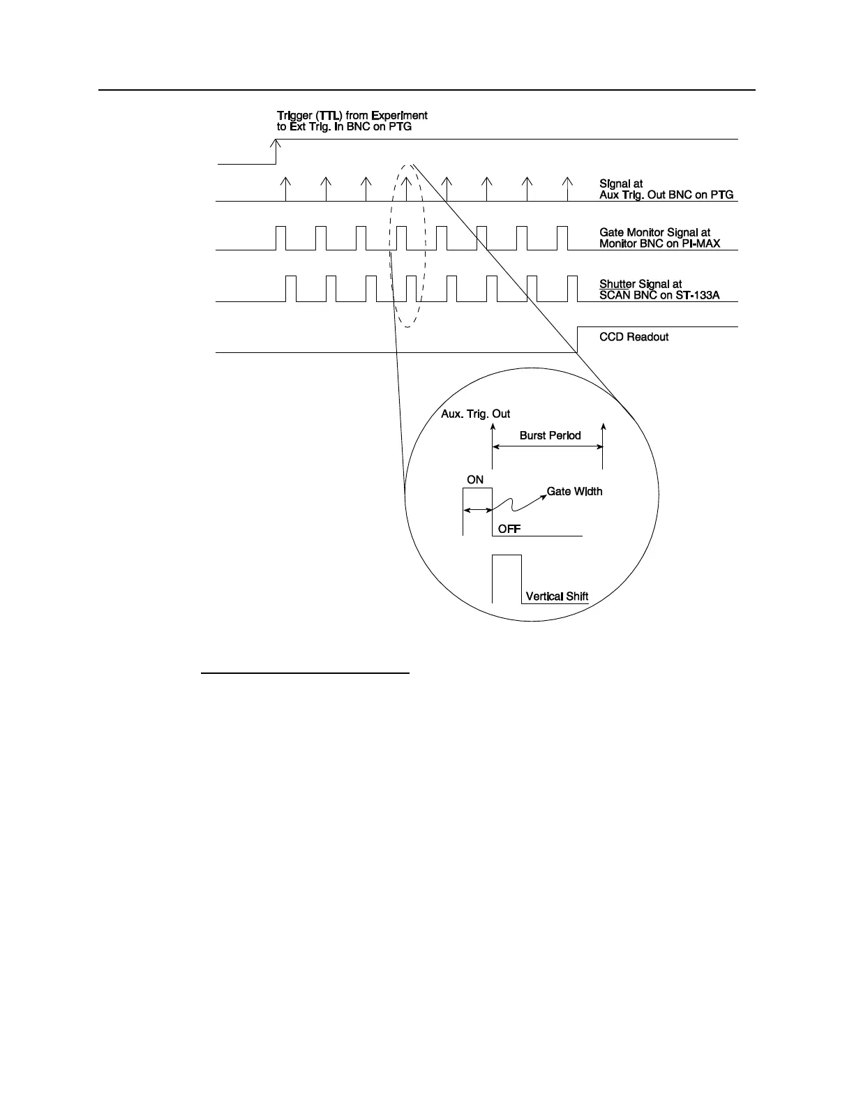
Figure 79. Timing Diagram: Experiment 1
Experiment 2: Multiple Trigger
A trigger, either internal or external, is required for each vertical shift "window" of the
CCD. The PTG generates the gate pulse and an internal sync for each incoming trigger.
The CCD vertical shift is driven by the internal sync of the PTG. Figure 80 is a timing
diagram for Experiment 2.
Hardware Connections
User's trigger pulse connected to Ext. Trig. In of PTG (optional)
PTG Settings
Trigger: External or Internal
Pulsing: Continuous with constant Delay or constant Width
Experiment Setup Settings
Main: Gate Mode
Timing: Multiple Trigger, -edge, disable Continuous Cleans, Shutter Control is
disabled open.