Chapter 7 Gated Operation with a PTG 99
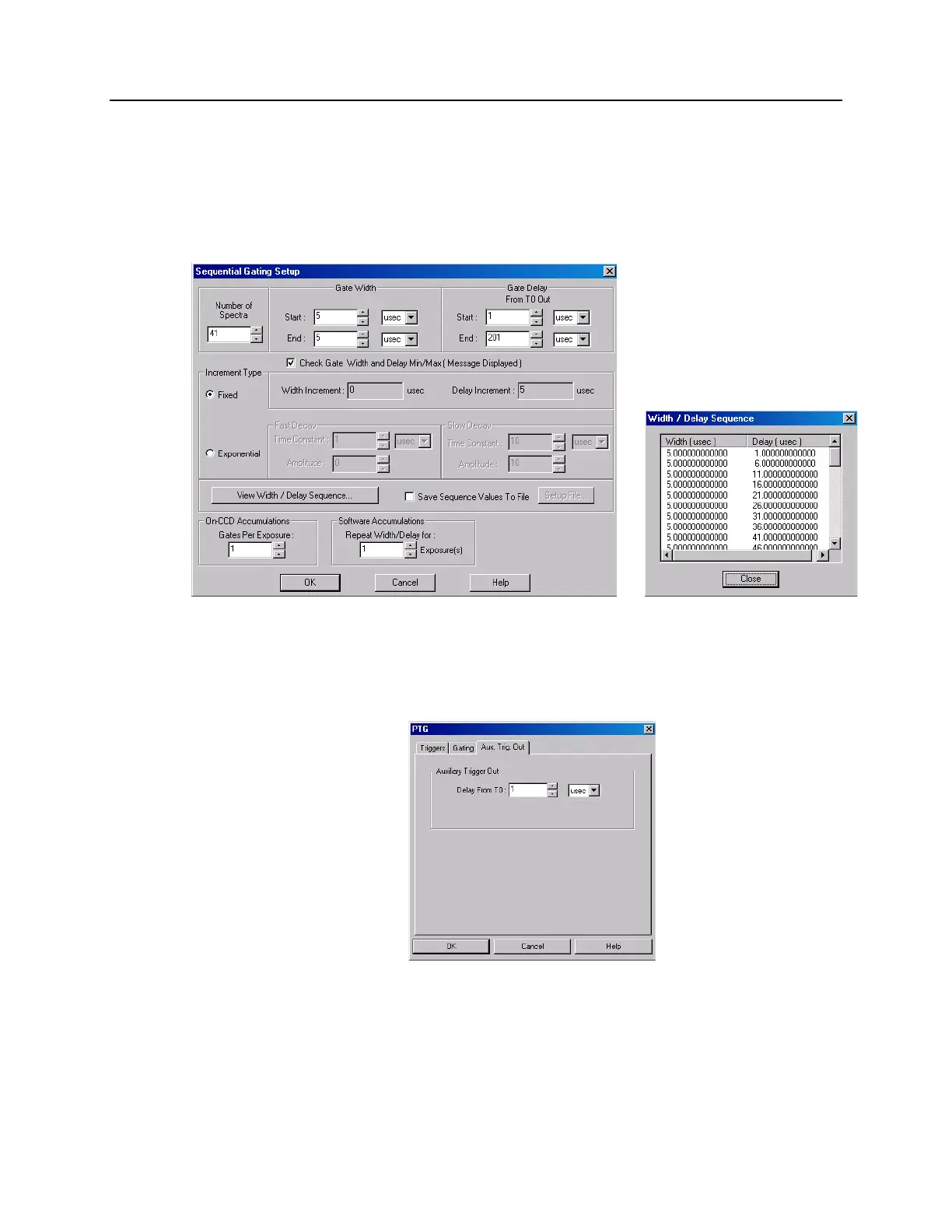
Enter the start and end durations for the gate delay. (For this experiment,
the start delay is 1 µsec and the end delay is 201 µsec.) Note that the
minimum gate delay for T0 is 1.5625 nsec.
Then select the number of exposures (in this case, 1 exposure).
To check the gate delay for each of the 41 spectra, click on "View
Width/Delay Sequence."
Figure 49. Sequential Gating Setup and Width/Delay Sequence dialog boxes
d. If you are using the Aux. Trig. Out signal from the PTG to trigger a piece of
equipment, then enter the Auxiliary Trigger Out delay time on the Aux.
Trig. Out tab page. See Figure 50.
Figure 50. Aux. Trig. Out tab page
e. Click on OK to program the pulser/timing generator.
11. Set up the experiment parameters from the Experiment Setup dialog box.
a. On the Timing tab page, change the timing as shown in Figure 51.