180 PI-MAX/PI-MAX2 System Manual Version 5.F
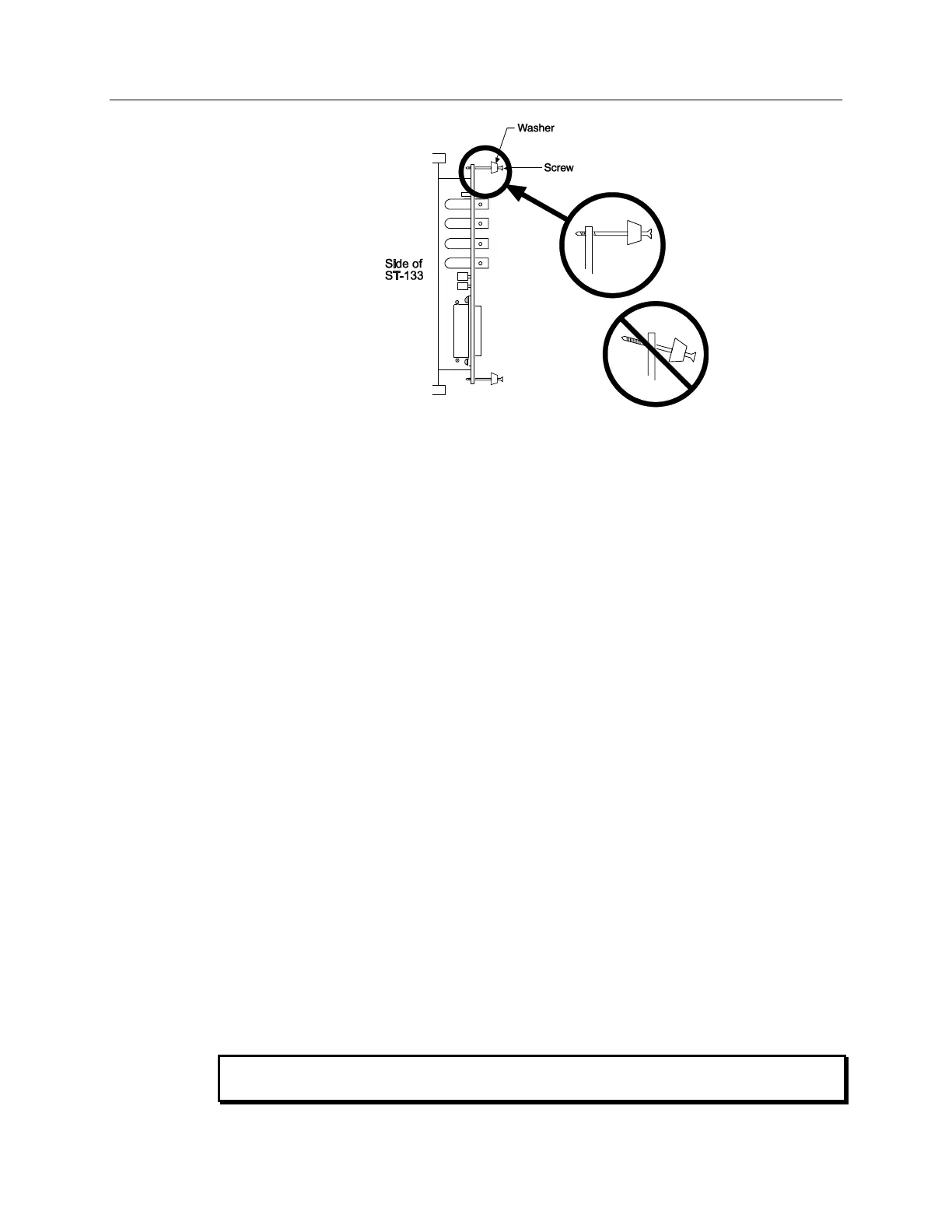
Figure 107. Module Installation
To Remove a Module:
1. Verify that the Controller has been turned OFF.
2. Rotate the two locking screws (one at the top of the module and one at the bottom)
counterclockwise until they release from the chassis.
3. Then, grasp the module and pull it straight out.
4. Set the module aside in a safe place. If you are replacing it with another module, as in the
case of exchanging a TAXI module for a USB 2.0 module, you may be able to use the
packaging from the new module to store the old module. This packaging is usually an
antistatic bag that will protect the module components from electrostatic discharge.
To Install a Module:
Installing a module is a bit more complex because you first have to be sure the locking
screws are aligned correctly. The following procedure is suggested.
1. Verify that the Controller has been turned OFF.
2. Remove the replacement module from its antistatic packaging. This packaging is
designed to protect the module components from electrostatic discharge.
3. Rotate the two locking screws counterclockwise until the threads on the screws engage
those of the module panel. See Figure 107. By doing this, the screws will be perfectly
perpendicular to the module panel and will align perfectly when the module is inserted.
4. Insert the module so the top and bottom edges of the board are riding in the proper
guides.
5. Gently but firmly push the module in until the 64-pin DIN connector at the back of the
module mates with the corresponding connector on the backplane, leaving the module
panel resting against the controller back panel.
6. Rotate the two locking screws clockwise. As the screws are rotated, they will first
disengage from the module panel threads, and then begin to engage those of the bracket
behind the controller panel.
Tighten the screws to where they are just snug. Do not tighten them any further because
you could easily bend the mating bracket.