98 PI-MAX/PI-MAX2 System Manual Version 5.F
6. Because there is a risk of overloading the camera in Shutter Mode, make sure
that the room or ambient illumination is low (i.e., you have difficulty seeing in
the room).
7. After setting the parameters and making sure the ambient light level is low, click
on Focus.
8. If the readout mode is currently set to “Use Region of Interest” on the Main tab
page, the camera will start acquiring data immediately. If the readout mode is
currently set to “Use Full Chip” you will be asked if you want to change the
setting to “Use Region of Interest” before focus mode is activated. Click on
“Yes” and the camera will begin acquiring data.
9. After you make sure that the camera is seeing in Free Run mode, stop data
acquisition.
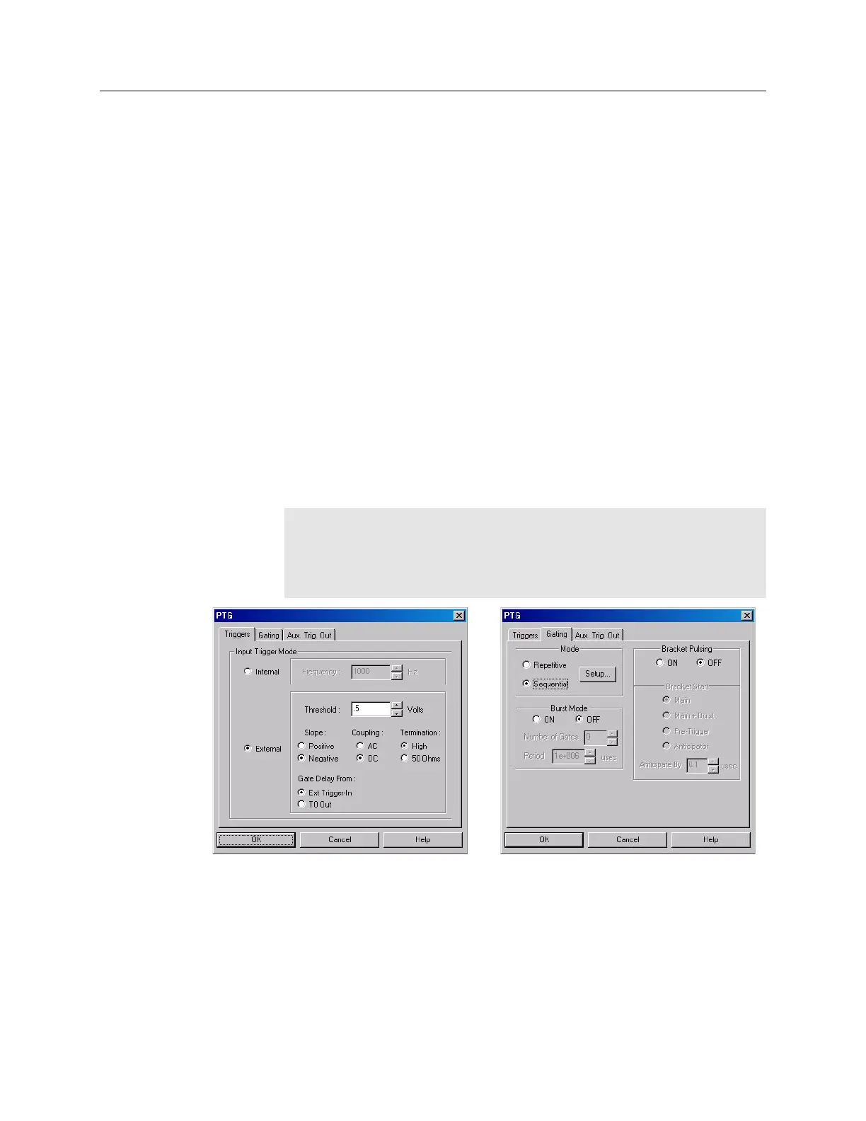
10. Set up the pulser (PTG). The following figures show typical examples of the
screens you would use to set up the PTG.
a. After selecting the PTG as the active pulser, click on "Setup PTG…".
Define the external trigger on the Triggers tab page. See Figure 48.
b. On the Gating tab page, select Sequential as the Active Mode and then
click on "Setup…". For this experiment both Burstmode and Bracket
Pulsing are OFF. See Figure 48.
Note: The Gate Delay From: choice will only appear if you have checked
"Use NVRAM Calibration (if present)" on the Get/Set Parameter and the
PTG Get/Set Parameter dialog boxes (accessed from the Diagnostics
menu). The NVRAM calibration is the factory calibration and will give you
the most accurate timing information gate width and delay.
Figure 48. PTG: Triggers and Gating tab pages
c. Click on "Setup…" and define the pulse sequence on the Sequential Gating
Setup dialog box. See Figure 49.
Enter the number of spectra to be acquired (in this case, 41).
Select "Fixed Increment".
Enter the start and end times for the gate width. (Since this experiment
requires a fixed gate width these values will be the same.)