Chapter 8 Gated Operation with a DG535 117
will mean inserting an additional delay of 500 ns to accomplish coincidence at the detector.
MCP bracketing should only be used in experiments where it is going to make a difference.
Note that background light need not be the limiting factor in measurements where MCP
bracket pulsing is unable to provide the required degree of rejection. In such
measurements, the option remains of installing an external shutter ahead of the PI-MAX.
Impact of Bracket Pulsing on Delay
If operating in the UV when bracket pulsing is activated (Gen II Intensifier only), the MCP
gate automatically brackets the photocathode gate pulse to further enhance the on/off ratio.
There is, however, a limitation of bracket pulsing that can complicate the coincidence of
the signal and gate at the camera. Because MCP bracket gating is much slower than
photocathode gating (500 ns is required to gate the MCP on and another 200 ns to gate the
MCP off at the end of the photocathode gate). As a result, MCP bracket pulsing should not
be used in experiments where the delay between the trigger and the photocathode gate is
less than 1 µs.
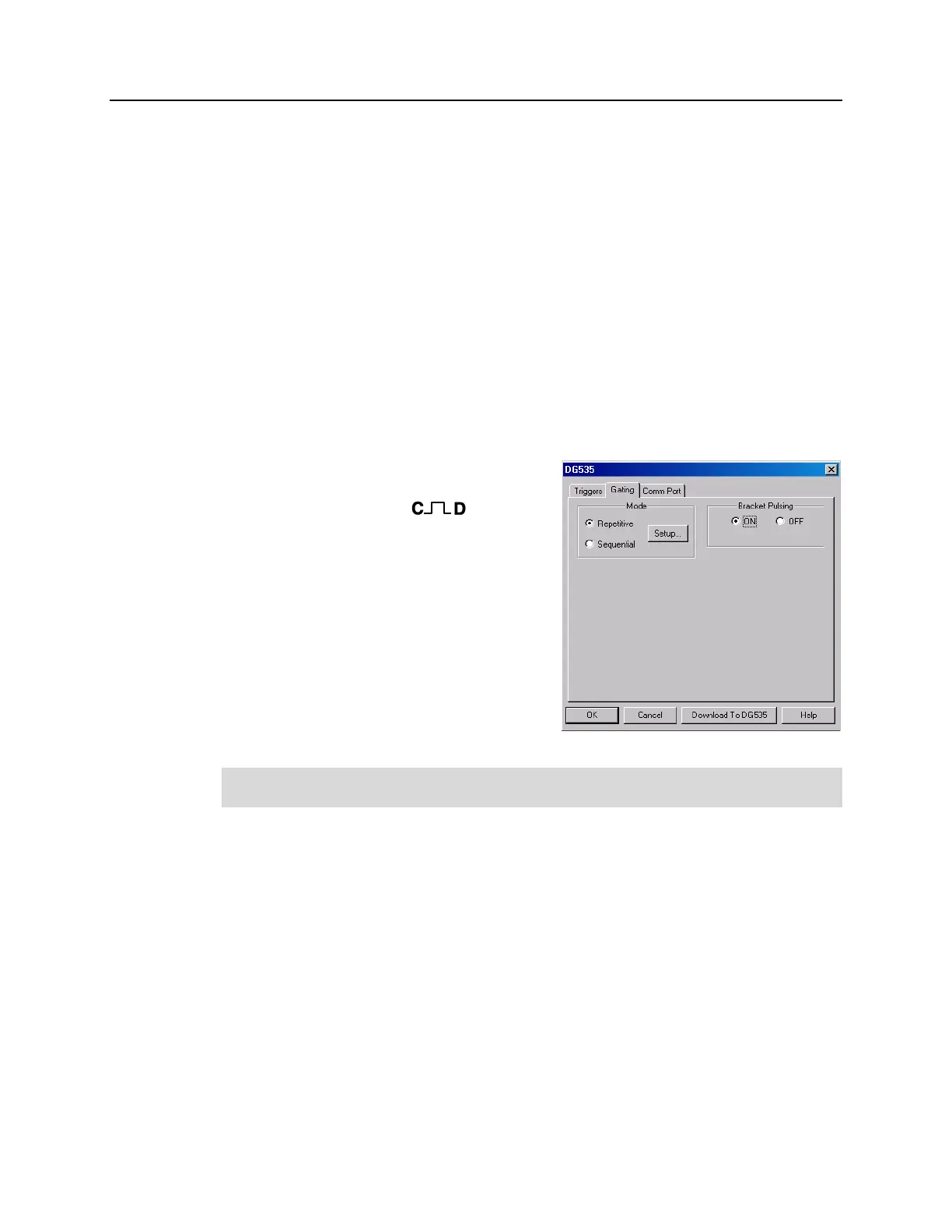
Setup
Implementing bracket pulsing involves
selecting the function in software (Figure 72)
and applying the DG535’s output via
the C+D-Gen II/A+B-Gen III cable to the
PI-MAX Timing Gen connector. The precise
timing required to implement the function is
automatically set according to photocathode
gate width and delay, with the limitation that
bracket pulsing should be deselected (or the
C+D-Gen II/A+B-Gen III cable disconnected)
if the delay between the trigger and the gate
pulse is less than 1 µs. This limit is imposed by
the relatively slow on/off time of the bracket
pulse function. It takes 500 ns to gate the
MCP on and another 200 ns to gate it off.
Figure 72. Gating tab page
Note: Because Gen III Intensifiers do not respond in the UV, bracket pulsing is not
available for these intensifiers.
MCP Gating
Introduction
MCP gating is only available with the PI-MAX
MG
system. This gating mode (not to be
confused with MCP bracket pulsing) provides you with a unique combination of
nanosecond-scale gating speed and high ultraviolet QE. Normally, such high UV QE is
only available in so-called slow gate intensifiers (i.e., those without a nickel underlay).
The PI-MAX
MG
applies the primary gating pulse to the MCP portion of the tube and, if
chosen by the user, applies the bracket pulse to the photocathode. Consequently, it
provides the full benefit of bracket pulsing along with enhanced QE.
The main limitations with this option are that there is a somewhat larger propagation
delay and larger optical FWHM than a standard fast gate PI-MAX. Quantitatively, the
propagation delay of the PI-MAX itself is in the 40 ns range compared to 10-12 ns for a
standard PI-MAX. Note that DG535 propagation delay is in addition to the 40 ns.