76 PI-MAX/PI-MAX2 System Manual Version 5.F
Photocathode stays biased
on for the exposure time
and is then biased off
System waits the shutter
compensation time for the
phosphor to decay
Photocathode is
biased on
Controller waits for
External Sync pulse
Shutter (Normal)
Photocathode is
biased on
Controller waits for
External Sync pulse
Shutter (PreOpen)
External Sync
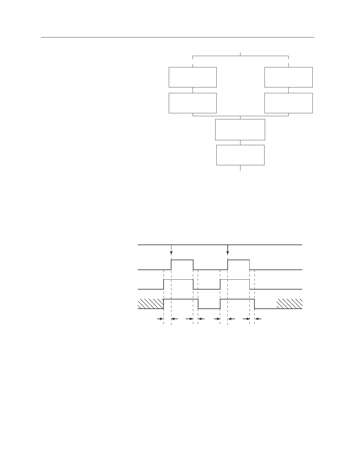
Figure 27 is a flowchart that
shows the sequence of actions
depending on the type of
Shutter Control. Figure 28 is a
timing diagram of the same
sequences with an External
Sync trigger active on the
negative edge. In the first setup
(Normal), the photocathode is
biased on when External Sync
goes low. Because it takes
some time to bias the
photocathode on, part of the
incoming signal may be missed
while this is happening. In the
second setup (PreOpen), the
photocathode is biased on when
the following conditions are
met: the Start Acquisition
command is received, clean
cycles finish, and the
NOT SCAN signal goes high. The advantage is that the
photocathode is already biased on when the exposure (triggered by External Sync)
begins. The disadvantage is that ambient light is no longer being blocked from the array.
Continuous cleans provide a way to get rid of the signal that accumulates on the array
during that period.
Image
Acquired
Clean
Cycles
CCD
Readout
External Sync
(Negative polarity)
ET
t
c
t
w
NOT SCAN
Clean
Cycle
Photocathode
Shutter (Normal)
Biased
On
Photocathode
Shutter (Preopen)
Biased
Off
Biased
On
Biased
Off
Biased
On
Biased
Off
Biased
On
Biased
Off
Number of Images = 2
t
w
= time between Start Acquisition command and Photocathode
bias on in Shutter (Normal)
ET = exposure time set in Experiment Setup
t
c
= 6 msec shutter compensation for Electronic shutter
CCD
Readout
ET
t
c
t
w
Image
Acquired
Figure 28. Timing Diagram: External Sync
Figure 29 shows a timing diagram that is basically the same as the one shown in Figure 28.
The difference is the continuous cleans (indicated by the shaded areas labeled CC) that now
occur during t
w
(the
waiting period during which External Sync will be accepted).
Figure 27. Flowchart of Two External Sync Timing Options in
Shutter Mode