Chapter 5 General Operation Factors 61
After the first row is moved into the shift
register, the charge now in the shift register
is shifted toward the output node, located at
one end of the shift register. As each value
is "emptied" into this node it is digitized.
Only after all pixels in the first row are
digitized is the second row moved into the
shift register. The order of shifting in our
example is therefore A1, B1, C1, D1, A2,
B2, C2, D2 ....
After charge is shifted out of each pixel the
remaining charge is zero, meaning that the
array is immediately ready for the next
exposure.
A subsection of the CCD can be read out at
full resolution, sometimes dramatically
increasing the readout rate while retaining the
highest resolution in the region of interest
(ROI). Note that some overhead time is
required to shift out and discard the unwanted
pixels.
Figure 18. Full Frame at Full Resolution
Interline Readout
In this section, a simple 6 3 pixel interline CCD is used to demonstrate how charge is
shifted and digitized. As described below, two different types of readout, overlapped and
non-overlapped can occur. In overlapped operation, each exposure begins while the
readout of the previous one is still in progress. In non-overlapped operation (selected
automatically if the exposure time is shorter than the readout time) each readout goes to
completion before the next exposure begins.
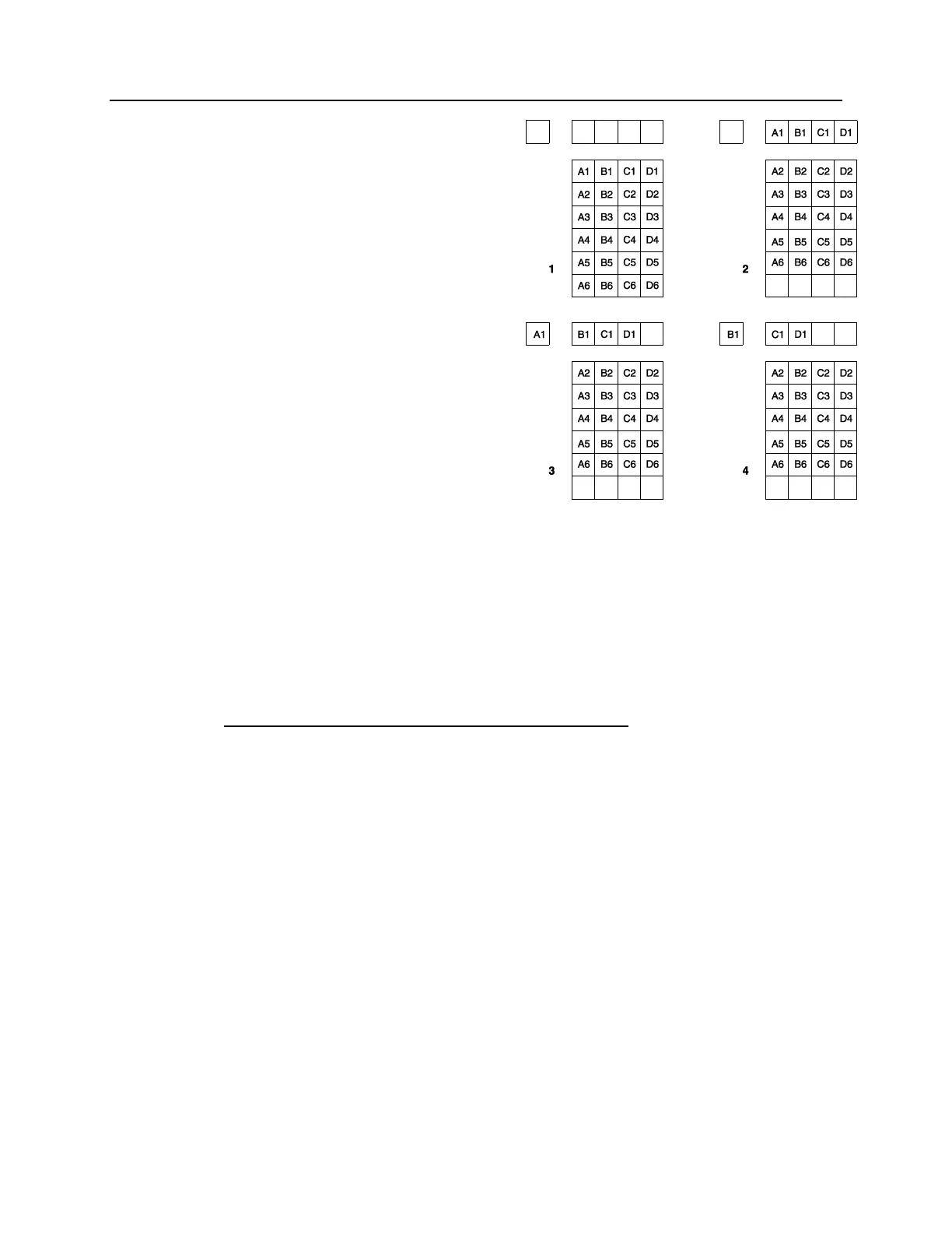
Overlapped Operation Exposure and Readout
Figure 19 illustrates exposure and readout when operating in the overlapped mode.
Figure 19 contains four parts, each depicting a later stage in the exposure-readout cycle.
Eight columns of cells are shown. Columns 1, 3, and 5 contain imaging cells while
columns 2, 4, and 6 contain storage cells. The readout register is shown above the array.
Part 1 of the figure shows the array early in the exposure. The imaging cells contain charge
proportional to the amount of light integrated on each of them. The storage cells are empty
because no charge has been transferred to them. The arrows between adjacent imaging and
storage cells indicate the direction the charge will be shifted when the transfer occurs.
Part 2 of Figure 19 shows the situation early in the readout. The charge in the imaging
cells has been transferred to the adjacent storage cells and up-shifting to the readout
register has started. Note that a new exposure begins immediately.
Part 3 of Figure 19 shows the transfer to the output node. The lowermost cell in each
column is shown empty. Each row of charges is moved in turn into the readout register,
and from there to the output node and off of the array for further processing. The process
continues until all charges have been completely transferred out of the array. The imaging
cells continue accumulating charge throughout the readout process. Integrating in this
way while the readout takes place achieves the maximum possible time efficiency.