Chapter 14 System Component Descriptions 163
PI-MAX to PTG: This 15' cable (6050-0406) is required if the system includes a
PTG. This cable interconnects the Timing Gen connector on the PTG module
with the Timing Gen connector on the PI-MAX.
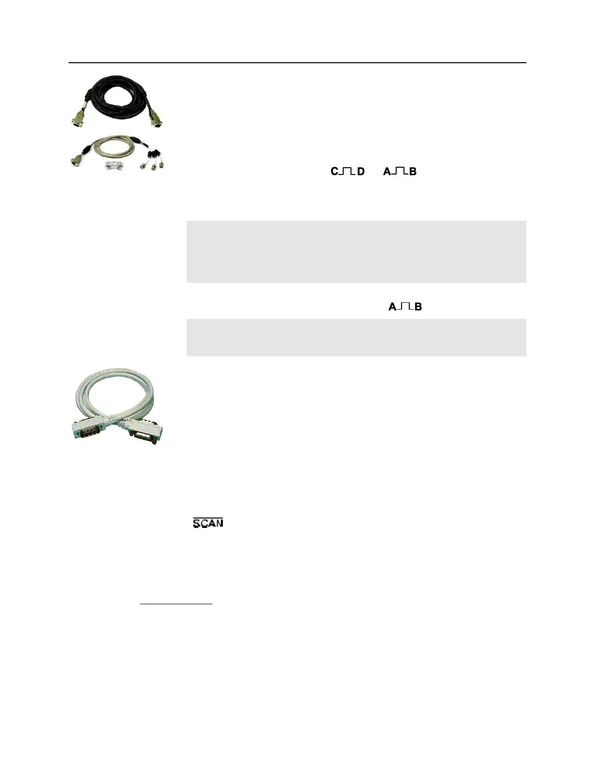
PI-MAX to DG535: This 6' cable (6050-0385) is required if the system includes
a DG535. This cable assembly includes a Filter (2550-0347) for CE-compliance.
The cable connects via the Filter to the DB9 Timing Gen connector on the back
of the PI-MAX, and to the A, B, and (or depending on the
intensifier type) BNC connectors of the DG535. The cable branches into three
BNC cables, one labeled A Start, one labeled B Stop, and the third C+D Gen
II/A+B Gen III.
Gen II Notes:
1. When this cable is left unconnected, the MCP will be biased
continuously ON. Normal photocathode gating will remain functional.
2. Leave this cable unconnected if the delay between trigger in and the gate
pulse is less than 1 µs.
For proper operation of a Gen III Intensified camera when gating, connect the
C+D-Gen II/A+B-Gen III cable to the DG535 BNC connector.
Gen III Note: Bracket pulsing is not allowed with Gen III Intensifiers. These
Intensifiers do not respond in the UV, negating any possible advantage to
bracket pulsing.
DG535 to Computer: This 4 meter cable (6050-0170) is required if the system
includes a DG535. This is a standard IEEE 488 GPIB cable. It connects the IEEE-
488 GPIB Std Port connector on the back of the DG535 to the interface
connector of the computer's IEEE-488 GPIB Interface card. The DG535
parameter values are set by sending commands to the DG535 from the computer
via the application software (WinView/32 or WinSpec/32). Note that local
vendors may be able to supply the GPIB cable.
DG535 to Controller BNC cables:
Cable connects BNC D output of the DG535 to the Controller's Ext. Sync
input. Tells the Controller to initiate an expose-readout cycle.
Cable connects the Controller's Shutter output signal (provided at ST-133's
Output) to the Inhibit input of the DG535 (must be equipped with
inhibit option). Inhibits the DG535 (and thus PI-MAX gating) during
readout.
Note that BNC cables may be available from local vendors. It is generally a
good idea to have spare BNC cables on hand.
Other Cables
Other cables may also be required depending on the system requirements. For example,
there may be a BNC cable from the laser pre-trigger output or other master timing source
to the Trig In BNC connector of the DG535. Note also that the DG535 provides a T0
output that, although not required by the PI-MAX or Controller, could be used to trigger
or gate other system components. If the system includes a computer-controlled
spectrograph, an additional cable would be required to connect the spectrograph with the
computer.