ROTALIGN
®
Ultra iS Shaft handbook
148
Without the spacers, there would be no direct contact between the faceplate and the
coupling surface surrounding the bolt holes – exactly the location where the faceplate
and coupling are being joined.
The centre part of the coupling face must not be used as a reference surface.
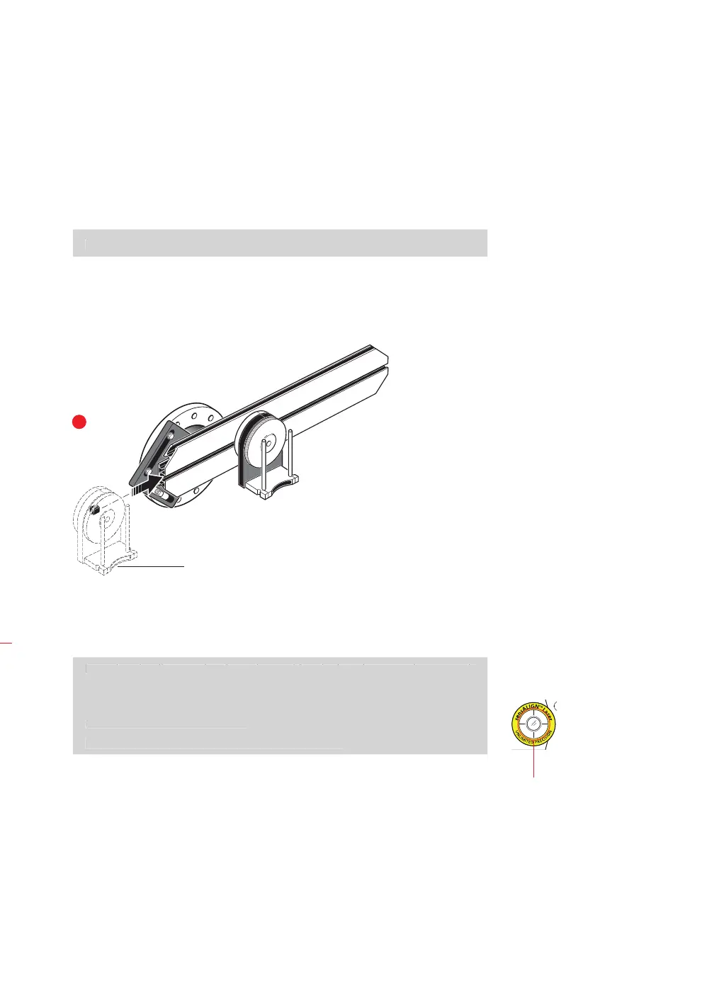
6.2.2 Mounting the laser holder assembly on to the rail
1. Loosen the handwheel slightly, then slide the laser holder assembly down the
center groove of the rail, with the T-nut acting as a guide (see figure
2a).
6.2.3 Mounting and adjusting sensALIGN laser
1. Slide the distance plate down the support posts.
Note that the distance plate is used to position the laser beam on the same axis
as the rotational axis of the laser holder.
Prior to mounting sensALIGN laser, adjust the two yellow beam position
thumbwheels to center the laser ‘bulls-eye’ as accurately as possible. This ensures
that the laser beam is emitted as straight as possible.
The coupling shown
previously has a raised
face flange. The provided
spacers are used to create
a three-point plane to
ensure that the faceplate
and the coupling face,
which is the reference
surface are joined
together.
Note
The centre part of the couplin