165
8. Loosen the flange bolts and perform offset corrections in the 0 to 6 and 9 to 3
o’clock directions while monitoring the live Move on the screen.
› Corrections should be brought as close as possible to zero.
› Use appropriate tools (e.g. jackscrews) to position the machine.
› Take care not to let the shims slip out of place during lateral positioning.
9. When offset is in tolerance, tighten the flange bolts. Remeasure to check if the
new alignment condition is in tolerance.
10. If not, repeat the above steps until alignment is in tolerance.
6.4 Flange-mounted horizontal machines
When machines are joined by means of flange, their alignment is determined by
inserting the proper combination of shims at the flange bolts and, depending on the
flange type, between the faces of the flanges. The requirements are quite similar to
those for aligning vertical machines.
When the shaft rotates around a horizontal axis, the electronic inclinometer detects
the rotational position during measurement, which may be taken in any desired
measurement mode.
Based on the measurements taken, the computer determines the thicknesses of shims
to be fitted between the flanges required to align the shafts.
6.4.1 Set-up
1. Mount sensALIGN laser and sensor on the shaft. sensALIGN laser mounts on the
left machine and sensALIGN sensor on the right. This arrangement is identical to
the standard ROTALIGN Ultra iS screen display for horizontal machines.
2. Switch ROTALIGN Ultra iS on by pressing
e and holding for a few seconds.
When the program manager screen appears, use the navigation keys to highlight
‘Shaft Alignment’. Press
e to access the application. The opening template in
the set-up screen appears.
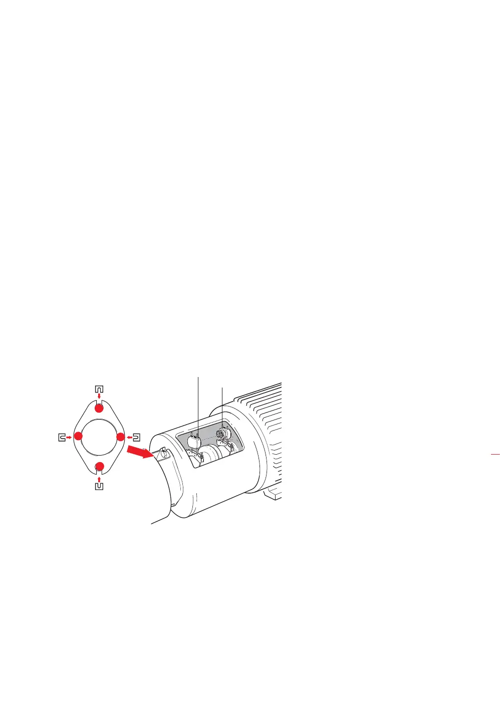
Laser
Sensor
Shown here are the
shimming locations for a
two-bolt flange, a special
case of the normal circular
flange shape.
End view of flange
(as seen from left)
Machine to be
aligned
Flange shimming positions 1-4
2
4
3
1
Flanged machines