143
6.1.2 How to align machinery trains
The following step-by-step approach is recommended for multiple element trains.
1. Measure alignment at each coupling
2. Display results and optimize corrections (by defining ‘stationary’ machine feet)
3. Align the two machines at the first coupling position (remount sensors if
necessary). The Live Move function is used to perform foot corrections.
4. Check alignment results
5. Align the two machines at the next coupling position, then repeat alignment
check
6. Repeat step 5 until all machines have been aligned.
6.1.3 Measurement
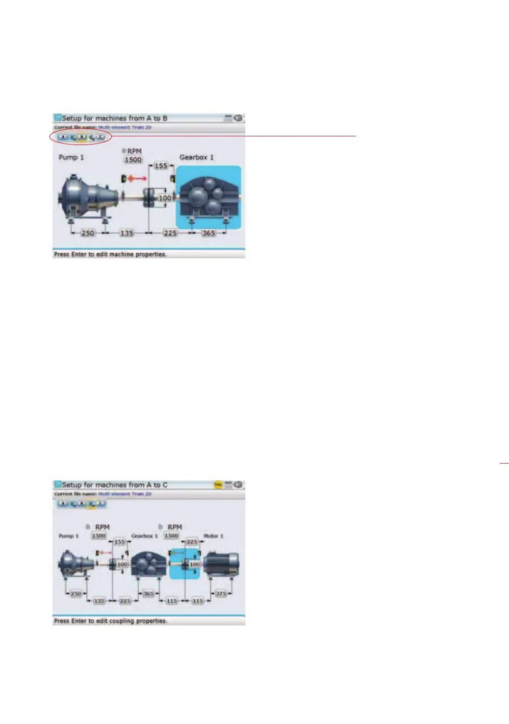
1. While in the set-up screen, use
f to zoom out the machine train. Pressing
the key repeatedly will zoom out until the entire machine train fills the display
screen.
2. Use
h/i to select the machine coupling to be measured first.
3. Ensure sensALIGN laser is mounted on the left side of the selected coupling.
A machine train of up to a
maximum of 14 machines
(13 couplings) can be
configured [Advanced /
Expert Shaft]. You may
view the entire machine
train at once through
the ‚zoom out‘ function
[
f], however, the
maximum number of
machines for which all
dimensions can be viewed
at one time is 5 machines
(4 couplings) Simply use
h/i to scroll through
the machines in the train.
To view any respective part
of the train closely, highlight
the section using
h/i
then zoom in by pressing
g.
The yellow focus shows
the machine train element
on which the blue cursor
is presently placed.
Machine train

 Loading...