ROTALIGN Ultra iS Shaft handbook
54
4.11 Laser beam adjustment
After entering all dimensions, proceed to adjust the laser beam such that it strikes the
sensALIGN sensor lens perpendicular to the lens surface.
1. Slide the sensALIGN laser dust cap to expose the aperture.
sensALIGN laser MUST remain off.
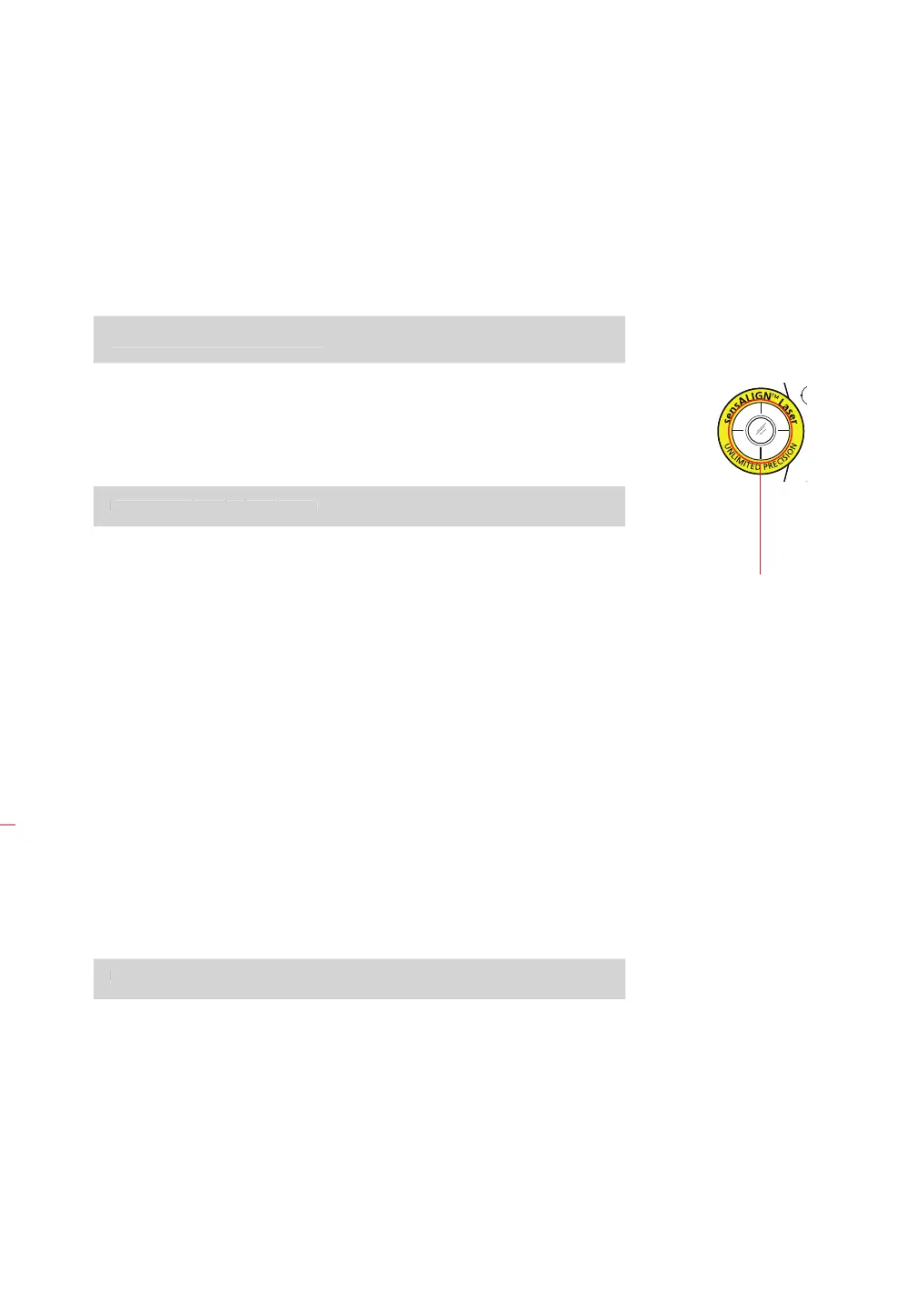
2. With the laser OFF, carry out a preadjustment to ensure that the laser beam will
be emitted perpendicular to the laser housing. Use the two yellow beam position
thumbwheels to centre the ‘bulls-eye’ as accurately as possible.
3. Press the ON/OFF push button switch to turn sensALIGN laser on.
Do not stare into the laser beam!
4. If both sensALIGN laser and sensor have been positioned at the same height and
roughly the same angular position during mounting (see section 4.5 – “Mount
sensALIGN laser and sensor” ), the laser beam should strike the sensor dust cap.
5. Slide the sensALIGN sensor dust cap to open the sensor lens and observe the
four sensALIGN sensor laser beam adjustment LEDs. If all four LEDs are blinking
green once every second, then the laser beam is correctly centered on the
sensor, and you may proceed with measurement (section 4.11).
6. If however, the laser beam is still not correctly centered, readjust the laser beam
using the yellow vertical and horizontal positioning thumbwheels. Observe the
four laser beam adjustment LEDs while adjusting the thumbwheels.
7. If all four LEDs are blinking green TWICE every second, the angle at which the
laser beam enters the lens is correct, but an offset is present. To eliminate the
offset, slide the sensALIGN sensor dust cap to cover the lens, then (if necessary)
loosen the chain type bracket supporting sensALIGN sensor and move the sensor
sideways. At the same time, if necessary, release the sensALIGN sensor clamping
levers and move the sensor upwards and downwards until the laser beam is
centred on the dust cap.
During this adjustment, DO NOT touch sensALIGN laser.
8. Open the sensor lens by sliding the dust cap and check the blinking of the four
LEDS. If all four are blinking green once every second, then the laser beam has
been correctly centred and measurement may proceed.
WARNING
sensALIGN laser MUST remain off.
“bulls-eye”
WARNING
Do not stare into t