ROTALIGN
®
Ultra iS Shaft handbook
160
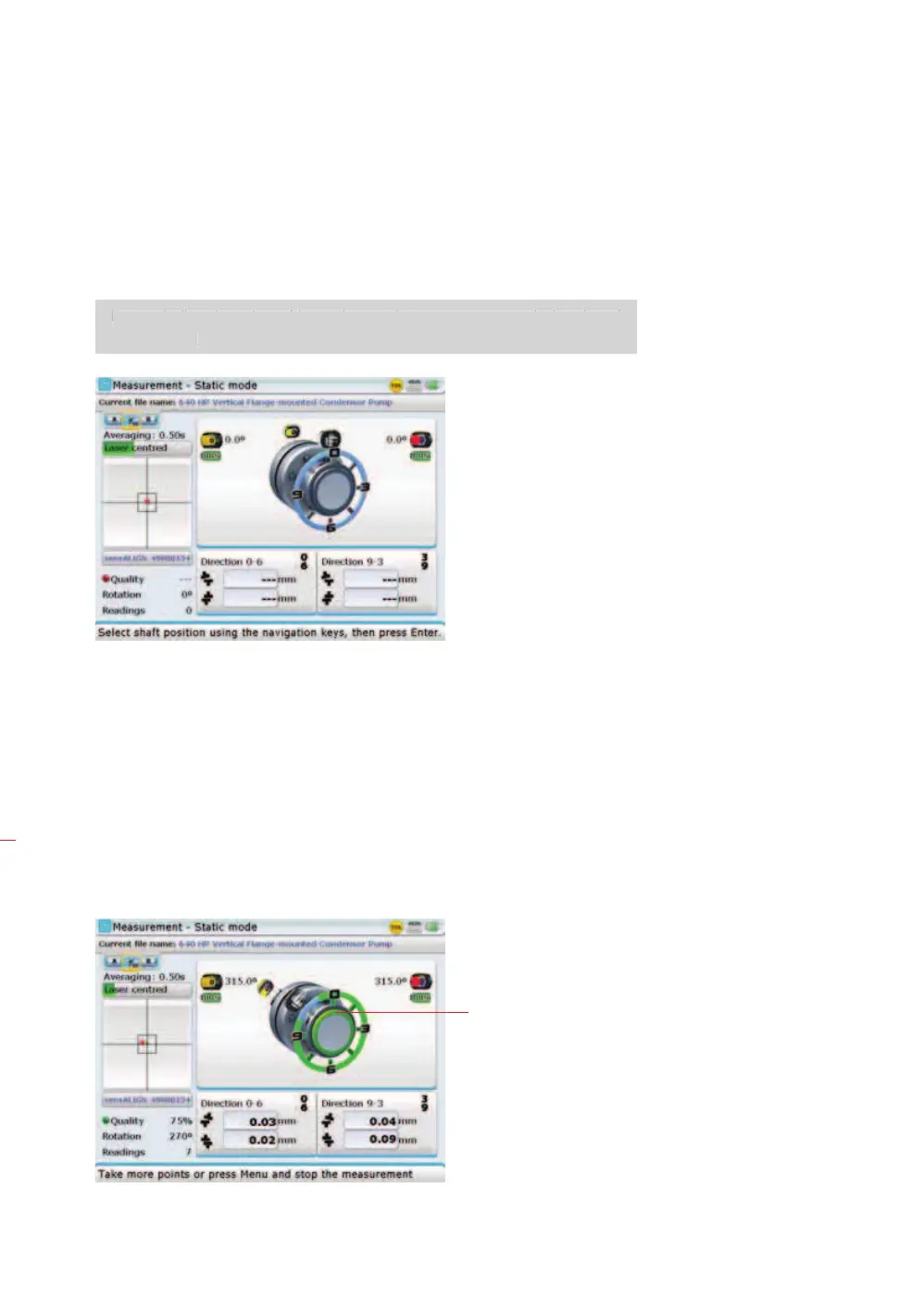
6.3.4 Measure
1. After entering the required dimensions, press
m and proceed to center the
laser beam.
For vertically oriented machine trains, static measurement mode is selected
automatically.
2. Rotate the shafts to the first measurement position. If using the coupling
housing numbering convention, the reference mark and the measurement
position 0 should be aligned or matched to each other.
3. Press
e to take the first measurement point.
4. Rotate shaft to the second measurement position (e.g. 1:30). If the chosen
measurement position does not correspond to the position selected automati-
cally on the display, use the navigation keys to manually position sensALIGN
sensor and laser at desired position on the display.
5. Take the maximum number of measurement points to maximize the quality of
results.
Note