147
6.2 Cardan shaft alignment
This section describes the alignment of cardan shafts using the cardan shaft bracket
Lite ALI 2.874 SETIS in conjunction with ROTALIGN Ultra iS. Cardan drives are installed
and operate with a large offset between the driver and the driven shaft. The spacer
shaft is set at a minimum angle of usually 4° to 6° in order to ensure sufficient
lubricant circulation, which in turn prevents the universal joints from seizing. Excessive
misalignment of such a configuration leads to rapid fluctuation of the driven shaft
RPM during operation, which holds grave consequences for electronically-controlled
synchronous and asynchronous AC drive motors.
For smooth operation the machines should be aligned such that the driving and
driven machine shaft centerlines are parallel. Precise alignment reduces the rotational
irregularities of the cardan shaft to a minimum, so that the uneven bearing loading
during cardan shaft rotation is also minimized, the service life of the components is
extended and the chance of unexpected machine failure is reduced.
The measurement procedure described here allows precise measurement of machines
joined by cardan shafts over distances of up to 3 m (10 ft) and shaft offsets of up to
400 mm (15 3/4 in.) using ROTALIGN Ultra iS.
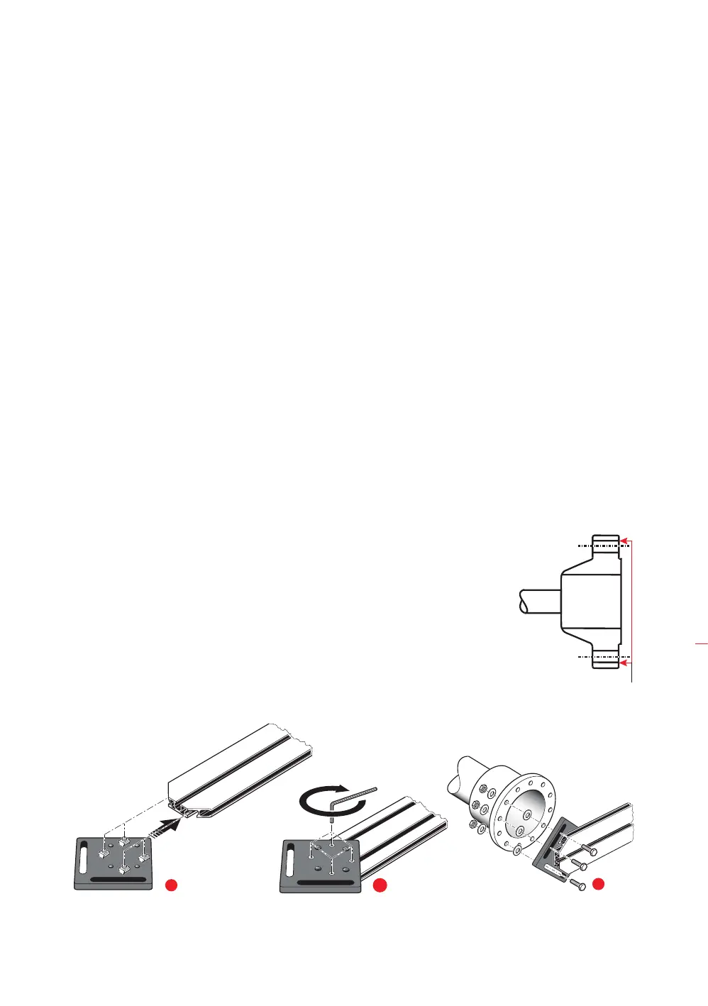
6.2.1 Mounting the faceplate to the rail
1. Slide the faceplate down the rail as shown in figure (
1a) below. The four T-nuts
should sit in the grooves.
2. After positioning the faceplate on the rail, tighten the four socket head screws
using the provided M6 allen key (see figure
1b).
3. Mount the bracket assembly to the coupling face of the non-rotatable shaft. If
the coupling face has a raised rim, the precision machined spacers are used as
shown in order to separate the bracket faceplate from the raised inner section of
the coupling face ( see figure
1c).
ROTALIGN Ultra iS Shaft
provides five bracketing
options with which cardan
shafts may be measured.
The measurement
procedure used for these
bracketing systems is
detailed in the ‘Cardan
shaft alignment getting
started’ DOC 99.201.en.
This handbook only
describes measurement
using the cardan shaft
bracket Lite ALI 2.874
SETIS.
Reference surface
1a
1b
1c
Cardan drives