169
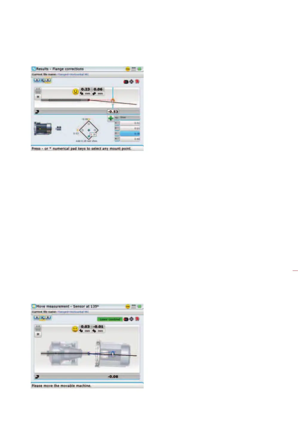
The flange is depicted as viewed from the right machine toward the left. The bolts
in the figure correspond to the bolts (or shimming positions) on the flange, with the
top position corresponding to number “1”. The respective offset appears on the top
half of the screen.
6.4.5 Shimming
Loosen the bolts and fit the shims according to the values given in the table. Try to
avoid any lateral movement of the machine while doing so. When finished, retighten
bolts.
6.4.6 Remeasure
Press
m and take a new set of readings before beginning offset corrections. The
results should now show little if any shimming corrections.
6.4.7 Live Move to eliminate offset
Start live Move using the “Results” screen context menu item ‘Move’.
Do not loosen the machine anchor bolts until live Move starts. Move the machine
laterally (for horizontal) while viewing the screen.
In this example, the
horizontal offset value is
0.06 mm positive.
The table on the right
lists the calculated shim
corrections. The interpreta-
tion of the shim corrections
has been described in
section 6.3.5.
Flanged machines