89
After finishing measurement, press
RES
to view results.
If only one shaft is not easily rotatable while the other can be freely rotated,
always mount the sensor on the nonrotatable shaft (use the magnetic sliding
bracket ALI 2.230). Do NOT mount the laser emitter on the not-easily-rotatable
shaft, even if this means setting up your laser and sensor opposite to the way
you normally would for alignment purposes. You can always invert the movable
and stationary machines by using the static feet utility in the results screen.
Enter all dimensions in accordance with your actual set-up, following the normal
orientation of the laser and sensor in the dimensions screen.
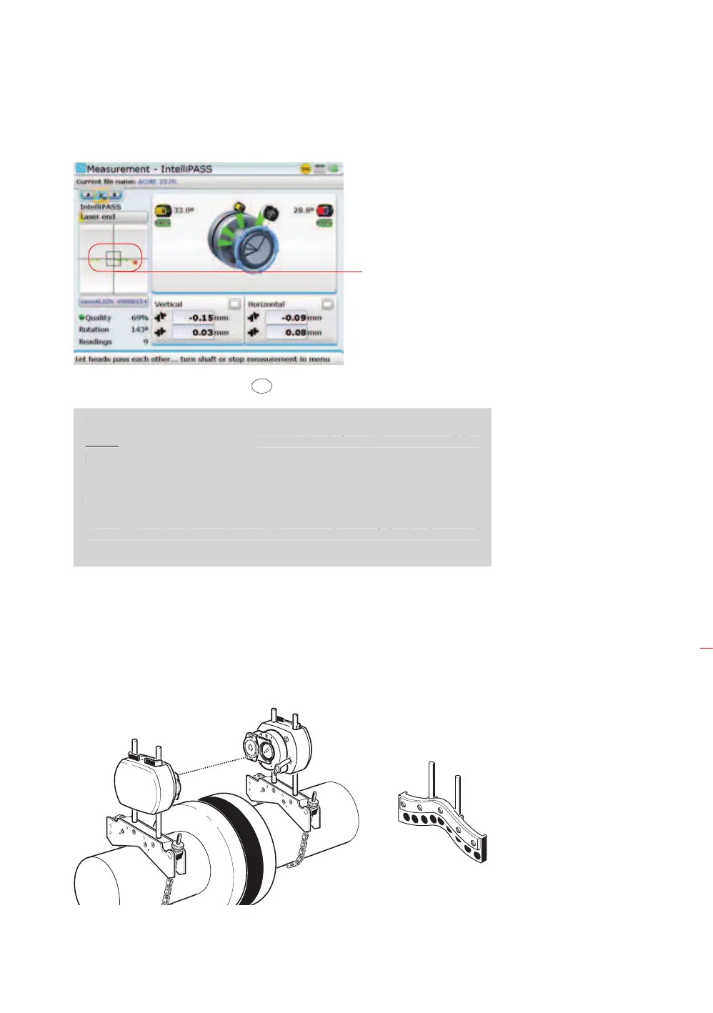
The path traced by the laser
beam as it passes the sensor
is plotted on the detector
display. Readings are taken
in the middle sector of the
detector surface. This is the
section where laser position
appears as green dots.
Readings are not taken
where laser position appears
as yellow dots.
Note
I
the laser and sensor in the dimensions screen.
It is recommended to take
several sets of readings
and then compare them
for repeatability in the
measurement table
(accessible from the
“Measurement” screen
context menu item ‘Table’.
If necessary average
together multiple sets
of readings for greater
accuracy.
Measurement modes
Uncoupled shafts:
Mount laser and sensor
using chain-type brackets For not easily rotatable
shaft(s):
Mount sensor using
magnetic sliding bracket
ALI 2.230.
Magnetic sliding bracket
ALI 2.230
sensALIGN laser
sensALIGN sensor