10-6 Requirements to the Mains Connection Rexroth IndraDrive
DOK-INDRV*-SYSTEM*****-PR02-EN-P
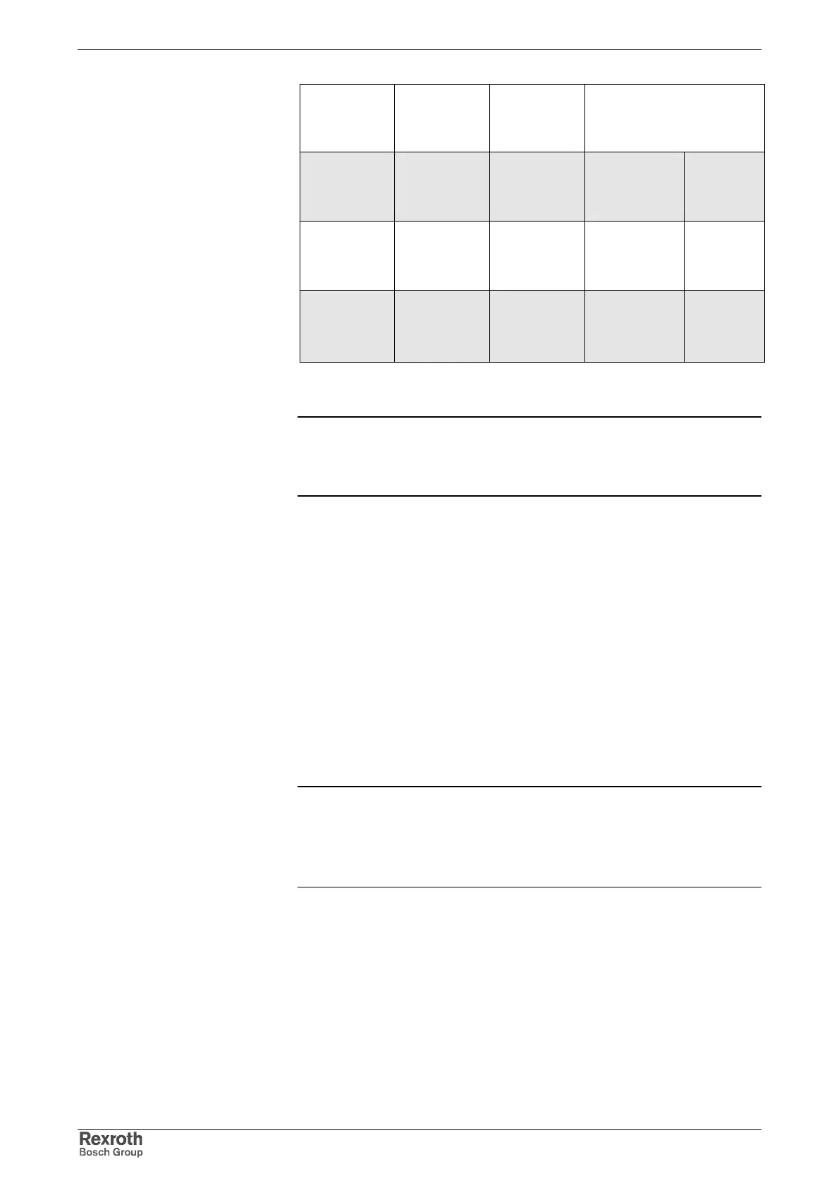
Kind of drive
controller
Realizable
THD of mains
current
Realizable
distortion
factor of
mains current
Drive controller or supply
unit with and without mains
choke
all devices THD>=50% K>=60%
HMV01.1E
HCS03.1
HCS02.1
without
device with
mains choke
THD< 48% K < 45 %
HMV01.1E
HCS03.1
HCS02.1
HNL01.1
devices with
Power Factor
Control (PFC)
THD< 13% K < 12 % HMV01.1R HNL01.1
Fig. 10-11: Realizable THD/distortion factor for drive controllers
Note: The allowed distortion factors can be achieved with the
indicated combinations of drive controller and mains choke.
Observe the assignment of mains choke to drive controller in
the corresponding Project Planning Manual.
We recommend the following procedure for selecting the required mains
connection components.
1. Determine max. current I of mains connection. Note: Classification for
public mains according to European standards in
• I < 16 A (EN 61000-3-2)
• 16 A < I < 75 A (EN 61000-3-12)
• I > 75 A (at present, not defined by any standard)
2. Determine mains short-circuit power S
k
of mains at place of
destination of application (ask power supply company).
3. Determine sum of connected loads S
A
.
4. Determine ratio R
sc
.
5. Determine allowed THD or distortion factor K of mains current at
place of destination of application (ask power supply company).
6. Select appropriate mains supply unit with additional component.
Note: The table below does not replace the recommended
procedure.
The table is used for first estimation of maximum allowed
connected load S
A
at point of power supply connection in low-
voltage mains at known mains short-circuit power S
K
.
Selecting Mains Connection
Components