10-8 Requirements to the Mains Connection Rexroth IndraDrive
DOK-INDRV*-SYSTEM*****-PR02-EN-P
Max. allowed voltage unbalance Standard reference
3 % IEC 61000-2-4, class 3
Fig. 10-14: Maximum allowed voltage unbalance
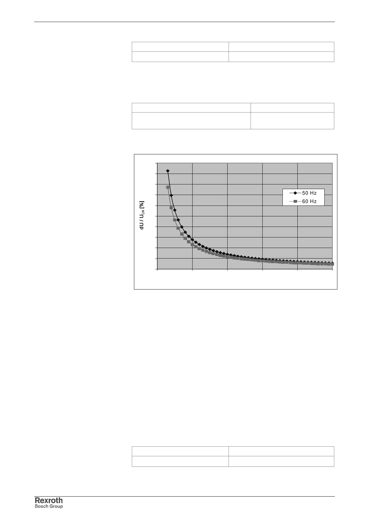
Commutation Drops
Drop on mains voltage Standard reference
depth 40% of mains amplitude, total surface
250% x degrees (see diagram)
IEC 60146-1-1, class 3
Fig. 10-15: Maximum commutation drops in % of mains voltage
Fig. 10-16: Maximum commutation drops in % of mains voltage
Short-Time Interruptions
A drive system is used for energy conversion and a voltage drop is a loss
of available energy.
The effect of the voltage drop (energy reduction) on the process cannot
be determined without detailed knowledge of the respective process. The
effect is a system and rating aspect and generally will be greatest when
the power demand (including the losses) of the drive system is greater
than the available power.
In the case of a voltage drop on the mains, thee voltage in the DC bus
can be reduced. This can cause the drive system to be cut off the mains
when voltage falls below certain levels and certain durations are
exceeded. When voltage returns the drive system has to be reactivated in
order to continue operation.
Harmonics of the Mains
The devices can be operated on a mains with the following THD:
Max. allowed THD Standard reference
10 % IEC 61000-2-4, class 3
Fig. 10-17: Maximum allowed harmonics
0
10
20
30
40
50
60
70
80
90
100
00,511,522,5
dt [ms]
d
U
/
U
L
N
[
%
]
50 Hz
60 Hz