7-20 Arranging the Components in the Control Cabinet Rexroth IndraDrive
DOK-INDRV*-SYSTEM*****-PR02-EN-P
7.3 Arranging Components in Control Cabinet from Mainly
Electrical Point of View
The section below contains information and recommendations on the
arrangement of the components in the control cabinet from mainly
electrical points of view. These points of view include aspects of
performance-dependent arrangement and installation in compliance with
EMC.
Performance-Dependent Arrangement
Performance-Dependent Arrangement
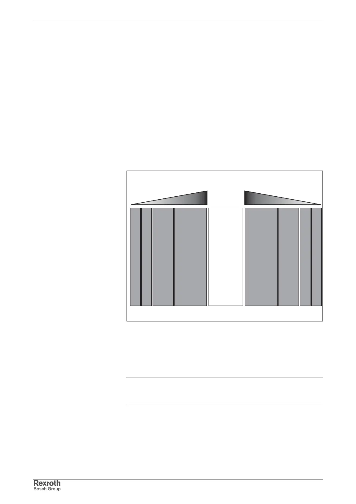
The HMV supply modules can supply HMS and HMD drive controllers on
both sides.
Arrange drive controllers according to their performance.
versorg_antrieb_sym.FH7
supply unit
drive controllers
high power low powerhigh powerlow power
drive controllers
Fig. 7-20: Example of an arrangement
Arrangement of Additional Components
• Arrange drive controllers with high performance as close to the supply
unit as possible. Ideally the drive controllers should be distributed
equally to the left and right side of the supply unit.
Note: If you operate HCS drive controllers with the type of mains
connection "central supply", arrange the supplied drive
controllers at the right side of the HCS drive controllers.
• Position DC bus capacitor unit next to drive controller with the
greatest DC bus continuous power.
• Position DC bus resistor unit next to drive controller with the greatest
regenerative power.
• Arrange HLR braking resistors in "standard" design above the HCS03
drive controller.