Rexroth IndraDrive Connections of the Components in the Drive System 12-5
DOK-INDRV*-SYSTEM*****-PR02-EN-P
DC Bus Connection (L+, L-)
CAUTION
Property damage in case of error caused by too
low line cross section!
⇒
Observe the current carrying capacity of the
connection lines at the DC bus connections.
⇒
Realize the connection lines at the DC bus
connections in such a way that they are protected by
the line protection at the mains connection of the
supply unit.
⇒
For the connection lines use cross sections at least
one grade bigger than the cross section of the lines
for mains connection of the supply unit.
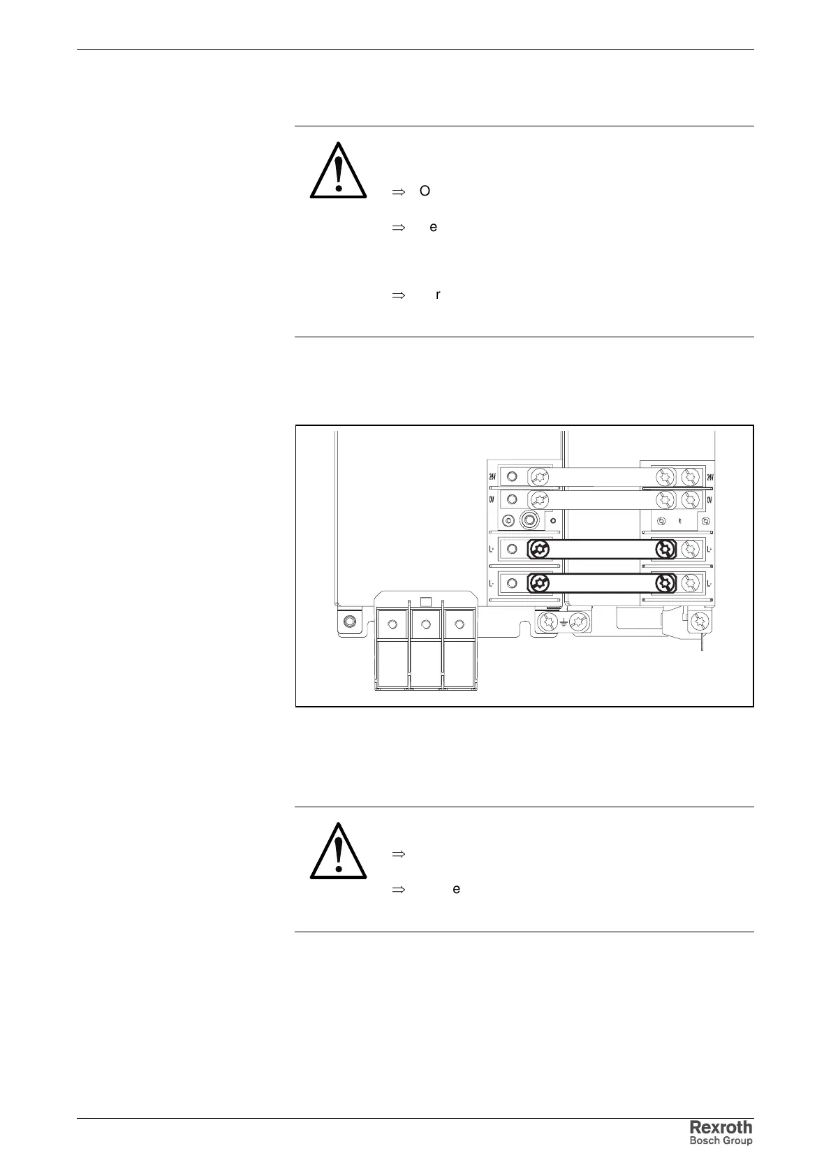
The figure below illustrates the connection point and connection of the DC
bus connections for system components HMV01, HMS01, HMD01;
HLB01.1D and HCS03 in single-line arrangement.
schienen_zwkreis
Fig. 12-5: Contact bars
For multiple-line arrangement of drive controllers the connection for DC
bus and control voltage supply is realized with cables.
CAUTION
Damage to the drive controller!
⇒
The DC bus connections of stacked drive controllers
must be correctly interconnected.
⇒
Connect L+ connections only to other L+
connections and L- connections only to other L-
connections.
The figures below illustrate the correct DC bus connection for stacked
drive controllers. The illustrated way of connection keeps bare wire
sections from being situated directly vis-à-vis. This avoids voltage arcing.
The cables have to be twisted.
Single-Line Arrangement
Design
Multiple-Line Arrangement