Rexroth IndraDrive Specifications for the Components of the Drive System 5-7
DOK-INDRV*-SYSTEM*****-PR02-EN-P
5.4 Supply Voltages
Control Voltage 24V Supply
For the devices of the IndraDrive range, the specifications for supply with
control voltage contained in the table below are generally valid.
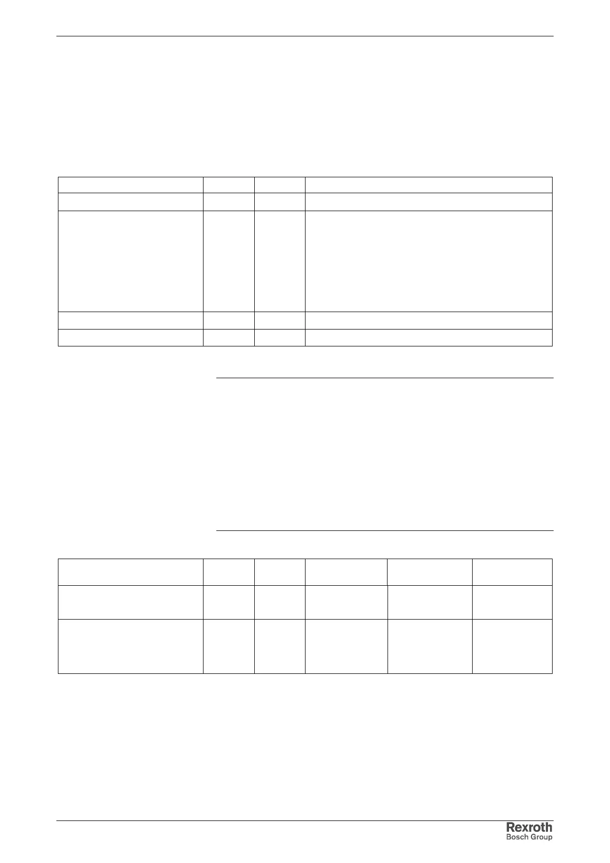
Standard range and extended range of control voltage
Designation Symbol Unit Value
standard range of control voltage U
N3
V
• 24 ± 5%
extended range of control voltage U
N3
V
• 24 ± 20%
(if no motor holding brake has to be supplied)
• If motor holding brakes are to be supplied, observe
the data of the motor documentation. The following
values are normally sufficient:
24 ± 5% at motor cable length < 50 m
26 ± 5% at motor cable length > 50 m
max. ripple content w - mustn't exceed the control voltage range
max. allowed overvoltage U
N3max
V 33 (max. 1 ms)
Fig. 5-9: Control voltage
Note: Overvoltage of more than 33V has to be discharged by means
of the appropriate electrical equipment of the machine or
installation.
This equipment includes:
• 24V power supply units that reduce incoming overvoltages
to the allowed value.
• Overvoltage limiters at the control cabinet input that limit
existing overvoltage to the allowed value. This, too, applies
to long 24V lines that have been run in parallel to power
cables and mains cables and can absorb overvoltages by
inductive or capacitive coupling.
Assignment of control voltage ranges
Designation Symbol Unit Supply modules Drive
controller
Additional
components
standard range of control voltage U
N3
VHMV-E
HMV-R
HLB01.1D
extended range of control voltage U
N3
V HMS01.1
HMD01.1
HCS02.1E
HCS03.1E
HLB01.1C
Fig. 5-10: Assignment of control voltage