Rexroth IndraDrive Arranging the Components in the Control Cabinet 7-17
DOK-INDRV*-SYSTEM*****-PR02-EN-P
7.2 Arranging Components in Control Cabinet from Mainly
Thermal Point of View
Multiple-Line Arrangement of Drive Controllers
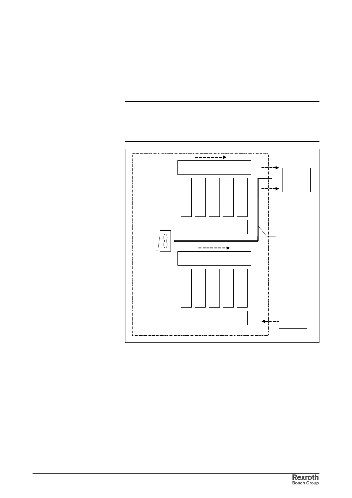
Control Cabinet with Multiple-Line Structure
Note: Particular attention should be paid to the maximum allowed air
intake temperature of components when they are arranged in
multiple lines in the control cabinet. Where necessary, cooling
air guides are to be provided with blowers specially used for
this purpose.
air guide
addit-
ional
blower
conveying direction of heated air
in flow-off area
conveying direction of heated air
in flow-off area
intake area of cooling air for
upper device line
intake area of cooling air for
lower device line
outlet air to
cooling unit
supply air
from cooling
Fig. 7-17: Example of arrangement for multiple-line structure with components