Rexroth IndraDrive Arranging the Components in the Control Cabinet 7-1
DOK-INDRV*-SYSTEM*****-PR02-EN-P
7 Arranging the Components in the Control Cabinet
7.1 Arranging Components in Control Cabinet from Mainly
Mechanical Point of View
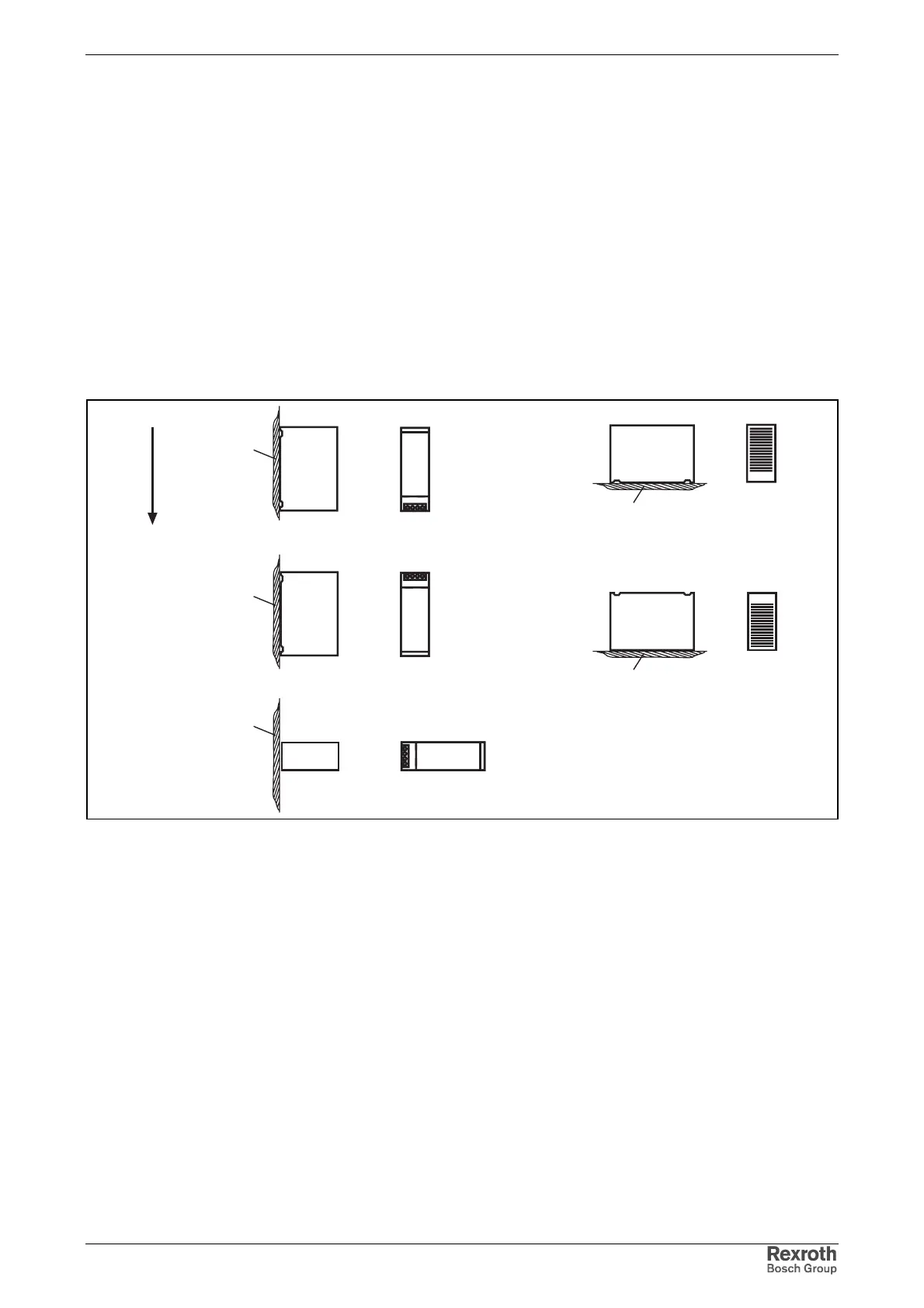
Position of Normal Use and Mounting Position
The drive controllers and additional components mustn't be operated in
all indicated positions of normal use and mounting positions. The allowed
positions of normal use and mounting positions are described in the figure
below.
g
G3
Rexroth
G2
Rexroth
G1
Rexroth
G4
G5
a
a
a
a
a
Einbaulagen.fh9
a mounting surface
g direction of gravitational force
Fig. 7-1: Positions of normal use and mounting positions
Brief Description of Positions of Normal Use and
Mounting Positions
• G1: Normal mounting position. The natural convection supports the
forced cooling air current. This avoids the generation of pockets of
heat in the drive controller. G1 is the preferred mounting position for
Rexroth IndraDrive components.
• G2: 180° to normal mounting position
• G3: turned by 90° from vertical to horizontal mounting position
• G4: bottom mounting, mounting surface on bottom of control cabinet
• G5: top mounting, mounting surface at top of control cabinet
Positions of normal use and mounting positions allowed for the individual
devices and reduction factors connected with them are contained in the
table below.
Mounting Positions
Normal Mounting Position
Allowed Mounting Positions