8-2 Electromagnetic Compatibility (EMC) Rexroth IndraDrive
DOK-INDRV*-SYSTEM*****-PR02-EN-P
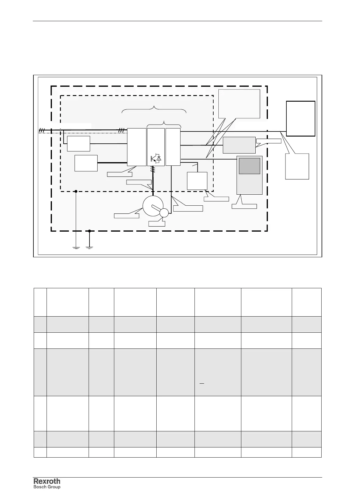
8.2 Noise Immunity in Drive System
The figure below illustrates the interfaces for definition of noise immunity
requirements in the drive system.
drive unit
enclosure port 3
signal interface
Cabinet/ Enclosure
encoder
motor
HMI or
control
device
Power
supply
unit
Power
unit
Control
unit
other electronic
or electrical
device
Other
power
24 volts
supply
drive module
External
Equipment
outside of the
machine unit
drive system/ machine
Other
electronic
device
signal interface
signal interface
power interface
power interface
power port (mains connection)
enclosure port 1
enclosure port 2
enclosure port 4
enclosure port 5
enclosure port 6
enclosure port 3
power interface
signal interface
Ports for process measurement
control lines
earth port
Application
Examples:
• Profibus
• Interbus
• DeviceNet
•
CANopen
Application Examples:
•
SERCOSinterface
• parallel and serial
interfaces
•
single
wire
connections
for
operation
Fig. 8-1: Basic structure and noise immunity
Table of noise immunity limit values
No Place of effect Pheno-
menom
Standard Conditions Coupling Test values
according
standard EN
61800-3
Perfor-
mance
level
Enclosure port IEC 61000-4-2 CD, AD 6 kV CD, 8kV AD,
if CD not possible
B
RF Field IEC 61000-4-3 Via antenna on
EUT
10 V/ m A
Power port Burst IEC 61000-4-4 length > 3 m mains connection
I < 100 A:
discoupling
network
I > 100 A:
clamp
4 kV/ 2,5 kHz
(clamp)
B
Surge IEC 61000-4-5 Only mains
connection;
I < 63 A,
light load test
Line – line 1 kV (2
Ohm)
Line – earth 2 kV
(12 Ohm)
B
IEC 61000-4-6 length > 3 m clamp 10 V, 0,15 – 80
MHz
A
Power Interface Burst IEC 61000-4-4 length > 3 m clamp B