6-18 Configuration of the Drive System Rexroth IndraDrive Rexroth IndraDrive
DOK-INDRV*-SYSTEM*****-PR02-EN-P
6.3 Allowed Combinations with Motor Filters HMF01
In conjunction with long motor cables, the steep switching edges at the
motor output of the drive controllers cause transient overvoltages and
high rise of voltage at the motor.
CAUTION
Damage caused by too high switching
frequency!
⇒
Only operate HMF01 motor filters up to the
maximum allowed switching frequency fs of 4kHz.
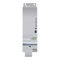
Drive Controllers HCS03 with HMF01
The combinations of motor filters and HCS03 drive controllers listed
below are functionally allowed.
Assignment of HMF01 Motor Filters to HCS03 Drive
Controllers
Motor filter HNK01 Drive controller
HMF01.1A-N0K2-D0045-.. HCS03.1E-W0070-
HMF01.1A-N0K2-D0073-.. HCS03.1E-W0100-
HMF01.1A-N0K2-D0095-.. HCS03.1E-W0150-
HMF01.1A-N0K2-D0145-.. HCS03.1E-W0210-
Fig. 6-16: Assignment HMF01 to HCS03
 Loading...
