12-8 Connections of the Components in the Drive System Rexroth IndraDrive
DOK-INDRV*-SYSTEM*****-PR02-EN-P
Control Voltage Connection (0 V, + 24 V)
Note: The input 0 V is connected in conductive form with the housing
potential. It is therefore impossible to use an insulation monitor
at +24 V and 0 V against housing.
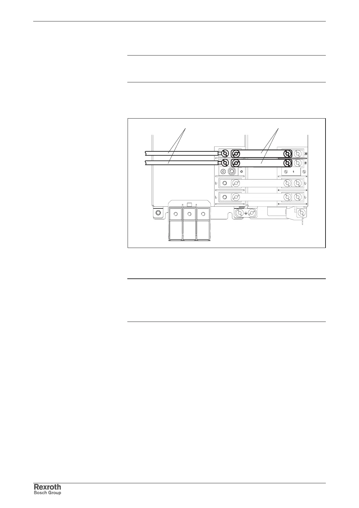
The figure below illustrates the connection point and connection of the
control voltage connections for system components HMV01, HMS01,
HMD01; HLB01.1D and HCS03 in single-line arrangement.
schienen_steuerspg
BA
A: cable (to source of control voltage supply)
B: contact bars
Fig. 12-8: Connection points and connections of control voltage
Note: Connect the system components HCS02 and HLB01.1C to
the control voltage supply. To do this connect each connection
point X13 to the control voltage supply.
Make use of the loop-through contacts and observe the
allowed load (see section).
The following figures show the correct control voltage connection for
stacked drive controllers. The illustrated way of connection ensures that
the touch guard can be correctly mounted and the required clearances
and creepage distances can be complied with.
The cables have to be twisted.
Single-Line Arrangement
Multiple-Line Arrangement