12-10 Connections of the Components in the Drive System Rexroth IndraDrive
DOK-INDRV*-SYSTEM*****-PR02-EN-P
Module Bus Connection X1
The module bus connection is used for signal exchange within the drive
system and has to be established via the supplied ribbon cables.
X1f2.FH7
X1 out X1 in
Fig. 12-11: X1
Note: When extension cables are used for the module bus, they
must be shielded. Their total length mustn't exceed a
maximum of 40 m.
The module bus extension accessory is available to extend
the module bus connection.
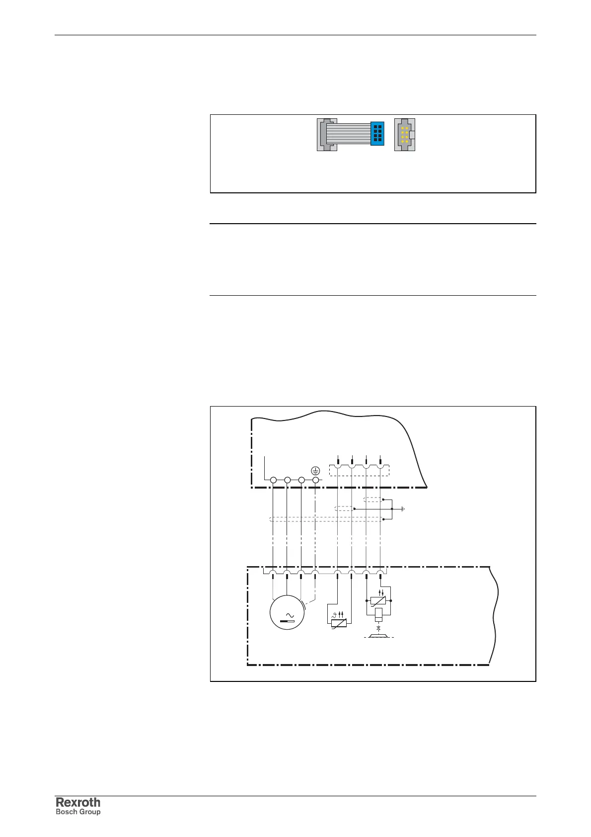
Motor Connection X5 and X6
• X5: Motor power connection (A1, A2, A3, equipment grounding
conductor)
• X6: Connection for motor temperature monitoring and motor holding
brake
x6_kabel_anschluss.FH7
X6
holding
brake
PTC /
NTC /
KTY84
(depends on motor type)
shield for
motor cable
AC motor
M
3
A
B
C
D
F
G
U
E
H
3
+24VBr
4
0VBr
1
MotTemp+
2
MotTemp-
A1 A2 A3
X5
Fig. 12-12: Motor connection
Graphic Representation