6-2 Configuration of the Drive System Rexroth IndraDrive Rexroth IndraDrive
DOK-INDRV*-SYSTEM*****-PR02-EN-P
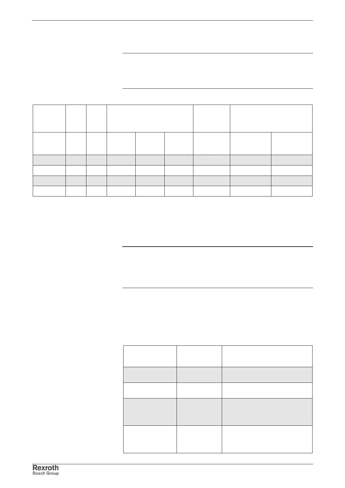
Allowed Components in Mains Connection Phase
Note: Operating supply units with regeneration back to the mains
requires components appropriate for this purpose in the
mains connection phase.
Make sure the type code sections -R or -E are matching.
Drive
controller
or supply
unit
Auto-
transf.
Isolat-
ing
transf.
Mains filter Mains filter
with
integrated
mains choke
Mains choke
DST DLT NFD03.1 HNF01.1*-
****-R****
HNF01.1*-
****-E****
HNK01.1
HNL01.1E;
HNL01.1E-****-
S
HNL01.1R;
HNL01.1R-****-
S
HMV01.1E
X X
--
-- X
--
X --
HMV01.1R
XX
--
X
-- -- --
X
HCS02.1E
X X X X
1)
X
1)
--
X
--
HCS03.1E
XX
--
X
1)
X
1)
XX
--
X: allowed
--: not allowed
1): take minimum capacitance against ground at DC bus into account
Fig. 6-3: Combination in mains connection phase
Minimum Capacitance against Ground
Note: Using HNF01.1 mains filters requires minimum capacitance
against ground at the DC bus of the connected drive
controllers.
The minimum capacitance is 330nF against ground at each of
L+ and L-.
The required capacitance at L+ and L- against ground is made available
by the drive controllers or supply units. For the value see the technical
data "capacitance power section against housing - C
Kop
"; the table below
contains an excerpt and indicates whether additional capacitances
against ground are required.
Drive controller /
supply unit
Capacitance
against housing
[ nF ]
Additional capacitances against
ground required?
HMS01 2 * 100 for supply via HCS;
not at HMV
HMD01 2 * 68 for supply via HCS;
not at HMV
HCS02 2 * 100 for less than 4 HCS02 drive
controllers;
for supply of less than 3
HMS01 / HMD01
HCS03 2 * 100 for less than 4 HCS03 drive
controllers;
for supply of less than 3
HMS01 / HMD01