Rexroth IndraDrive Requirements to the Mains Connection 10-3
DOK-INDRV*-SYSTEM*****-PR02-EN-P
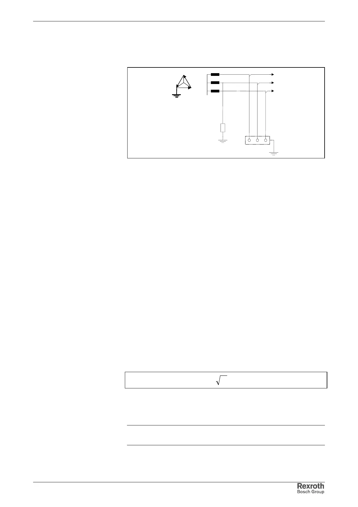
Mains with Grounded Outer Conductor (Corner Grounded Delta Mains)
E
I = isolation of all active parts from ground, connection of one phase –
generally phase v - to ground or via an impedance
T = exposed conductive parts directly grounded, independent of grounding of
current source (station ground)
Fig. 10-5: Mains with grounded outer conductor
Compliance with EMC requirements in this case is only possible under
restricted conditions. Can therefore only be used for industrial area with
its own mains.
10.3 Mains Short-Circuit Power and System Impedance –
Minimum Values at Connection Point
The maximum possible connected load at the connection point of the
mains depends on its mains internal resistance (system impedance) or its
minimum mains short-circuit power.
The following criteria are decisive:
• For the protection of devices a mains choke has to be connected in
the incoming circuit in the case of high mains short-circuit power Sk.
• In order to limit mains pollution and have sufficiently high voltage
available for realizing the drive performance, the mains has to have
sufficiently high mains short-circuit power with reference to the
connected load of the drive system.
The mains short-circuit power indicated the power at nominal voltage U
N
between the phases and the maximum mains short-circuit current I
K
at
the connection point:
KNk
IUS ×= 3
S
k
: short-circuit power of the mains
I
k
: short-circuit current
U
N
: mains voltage
Fig. 10-6: Mains short-circuit power
Note: For the mains short circuit power of the point of supply ask
your local power supply company.