11-14 Control Circuits for the Mains Connection Rexroth IndraDrive
DOK-INDRV*-SYSTEM*****-PR02-EN-P
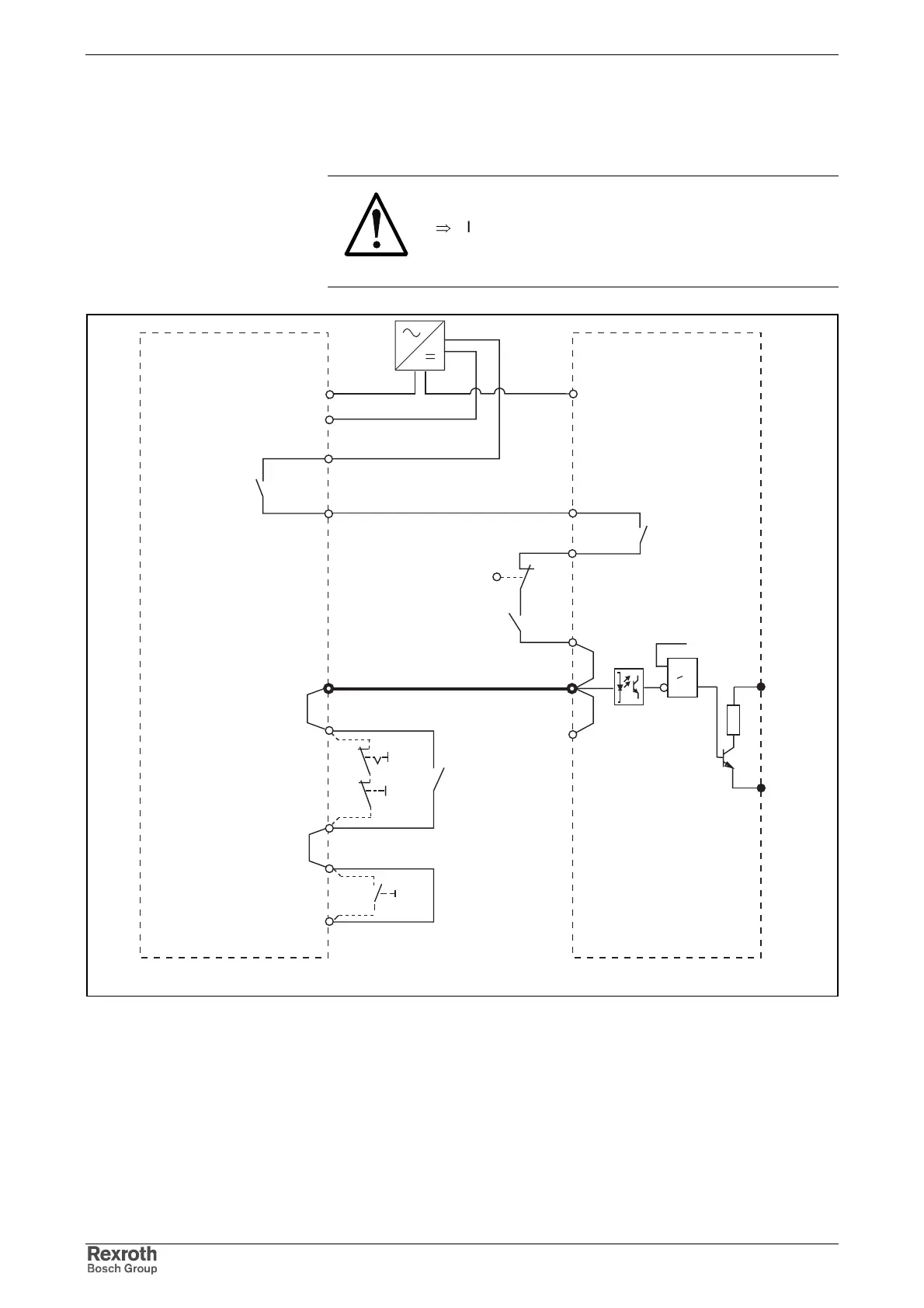
Combination of Supply Unit HMV01.1 and DC Bus Resistor Unit
HLB01.1D
CAUTION
Risk of damage to the device!
⇒
If the connection of HMV_X32/8 and HLB_X32/7 is
missing and the DC bus short circuit function is
used, the DC bus resistor unit can be damaged.
hlbd_hmv_installation.fh7
X32/9
X32/1
X31/6
X31/5
Bb1
X32/8
X32/7
A10
1)
1)
X32/6
X32/5
X32/4
HMV
HLB01.1D
X32/7
X32/1
X31/5
X31/6
X32/8
Bb2
X32/6
24V
0V
L+
L-
BRC
>1
S2
CNC
A10: E-Stop relay
BRC: (device-internal signal name) braking resistor control
CNC: lag error message of the control unit (only use contact that doesn't
open when the E-Stop switch is open)
S2: axis end position
1) control of K1 when there is no E-Stop relay used
Fig. 11-8: Wiring diagram HLB01.1D and HMV with HLB01.1D