Rexroth IndraDrive Requirements to the Mains Connection 10-7
DOK-INDRV*-SYSTEM*****-PR02-EN-P
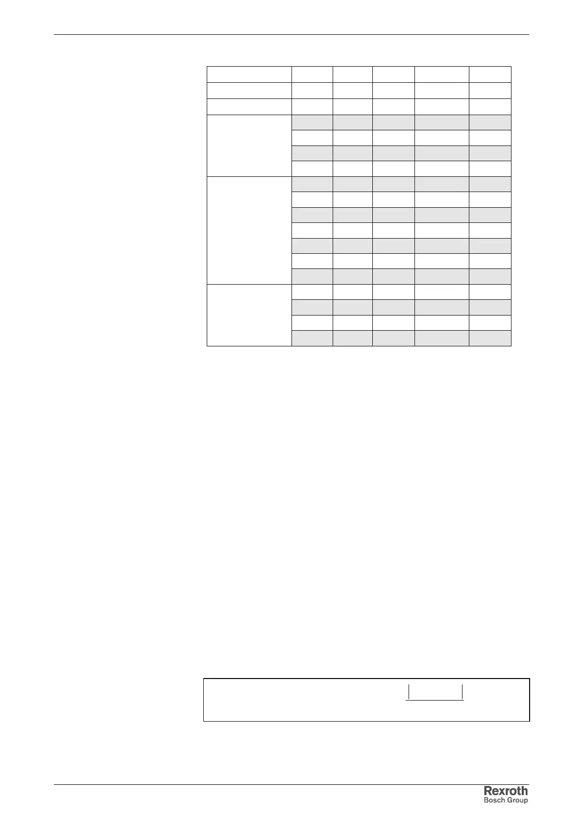
Rsc=250 Rsc=200 Rsc=100 Rsc=50
Classification
S
k
S
A
S
A
S
A
S
A
MVA kVA kVA kVA kVA
200 800,00 1000,00 2000,00 4000,00
150 600,00 750,00 1500,00 3000,00
100 400,00 500,00 1000,00 2000,00
1
rigid mains
50 200,00 250,00 500,00 1000,00
40 160,00 200,00 400,00 800,00
30 120,00 150,00 300,00 600,00
20 80,00 100,00 200,00 400,00
15 60,00 75,00 150,00 300,00
10 40,00 50,00 100,00 200,00
5 20,00 25,00 50,00 100,00
2
semi-rigid mains
4 16,00 20,00 40,00 80,00
3 12,00 15,00 30,00 60,00
2 8,00 10,00 20,00 40,00
1 4,00 5,00 10,00 20,00
3
non-rigid mains
0,6 2,40 3,00 6,00 12,00
R
SC
: mains short-circuit ratio
S
k
: mains short-circuit power
S
A
: connected load of all electric loads at connection point (apparent
power of fundamental wave)
Fig. 10-12: Maximum allowed connected load
10.4 Limit Values for Interference-Free Operation at Mains
The data below specify the limit values under which the drive system can
be operated at the mains without interference.
Mains Frequency Tolerance
see chapter 5 "Specifications for the Components of the Drive System"
Voltage Tolerances and Voltage Changes
see chapter 5 "Specifications for the Components of the Drive System"
Mains Voltage Unbalance
The voltage unbalance is described by a three-phase system consisting
of the combination of a
• clockwise a.c. system (positive-sequence system Um)
• counter-clockwise a.c. system (negative-sequence system Ug)
• d.c. system (U0)
AVE
AVEX
U
UU
unbalancevoltage
−
= 100%
Ux: phase-to-phase voltage with highest deviation from average value
U
AVE
:= (U
12
+ U
23
+ U
31
) / 3; U
12
, U
23
, U
31
being voltages between the
phases.
Fig. 10-13: Definition of voltage unbalance