12-2 Connections of the Components in the Drive System Rexroth IndraDrive
DOK-INDRV*-SYSTEM*****-PR02-EN-P
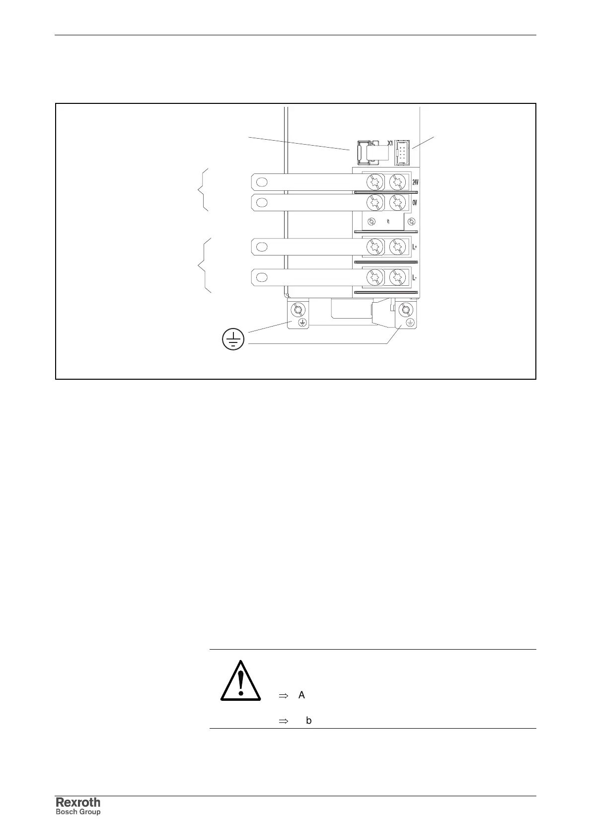
Position of System Connections
hms0070_frontf2
X1 out
+24 V
0 V
L+
L-
control voltage
DC bus
equipment
grounding
conductor
X1 in
Fig. 12-1: Connections at power section
Ground Connection of Housing
The ground connection of the housing is used to provide functional safety
of the drive controllers and protection against contact in conjunction with
the equipment grounding conductor.
Ground the housings of the drive controllers!
1. Connect the bare metal back panel of the drive controller in
conductive form to the mounting surface in the control cabinet. To do
this use the supplied mounting screws.
2. Connect the mounting surface of the control cabinet in conductive
form to the equipment grounding system.
Connection Point of Equipment Grounding Conductor and Equipment
Grounding Connections
The connection points of the equipment grounding conductors of the drive
controllers and their connection to the equipment grounding system are
important parts of electrical safety.
DANGER
Dangerous contact voltage at device housing!
Lethal electric shock!
⇒
Always operate drive controllers with connected
equipment grounding conductor.
⇒
Observe the explanations below.