Rexroth IndraDrive Configuration of the Drive System Rexroth IndraDrive 6-11
DOK-INDRV*-SYSTEM*****-PR02-EN-P
Combination HCS03 with HMS / HMD
Note: For combinations HCS03 with HMD01 and HMS01 we
recommend using brake chopper and braking resistor.
Using external DC bus capacitances C
Dcext
is not required.
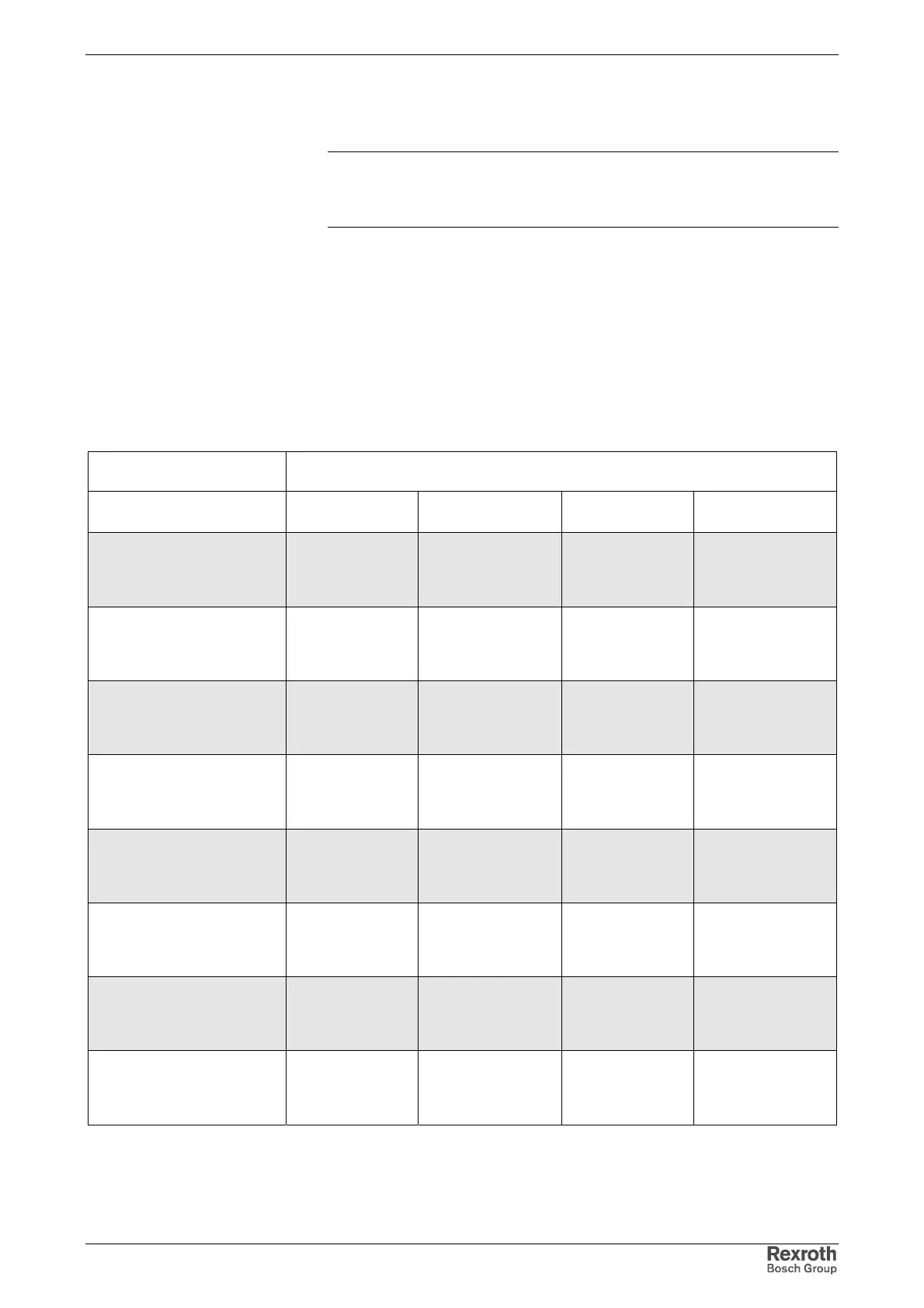
Central Supply HCS03 with HMS / HMD
Up to the indicated maximum allowed number of axes, drive controller
axes may be combined at the common DC bus according to the table
below.
You may make replacements up to the maximum allowed sum of the type
currents.
HMD01.1N drive controllers add the double value of their type currents to
the sum of allowed type currents.
Type of mains connect. (1)
Allowed IndraDrive M components at common DC bus with supply via HCS03.1E
devices
HMS01.1N- HMD01.1N-
max. allowed sum
of type currents
max. allowed
number of axes
central supply via
HCS03.1E-W0070 without
assigned mains choke
HNL01.1
up to W0054 up to W0036 120 12
central supply via
HCS03.1E-W0070 with
assigned mains choke
HNL01.1
up to W0054 up to W0036 270 12
central supply via
HCS03.1E-W0100 without
assigned mains choke
HNL01.1
up to W0070 up to W0036 270 12
central supply via
HCS03.1E-W0100 with
assigned mains choke
HNL01.1
up to W0070 up to W0036 270 12
central supply via
HCS03.1E-W0150 without
assigned mains choke
HNL01.1
up to W0070 up to W0036 270 12
central supply via
HCS03.1E-W0150 with
assigned mains choke
HNL01.1
up to W0070 up to W0036 270 12
central supply via
HCS03.1E-W0210 without
assigned mains choke
HNL01.1
up to W0150 up to W0036 270 12
central supply via
HCS03.1E-W0210 with
assigned mains choke
HNL01.1
up to W0150 up to W0036 270 12
--: not allowed
X: allowed
(1) for explanation see chapter
Fig. 6-11: Maximum number of IndraDrive M components at common DC bus