Rexroth IndraDrive Electromagnetic Compatibility (EMC) 8-3
DOK-INDRV*-SYSTEM*****-PR02-EN-P
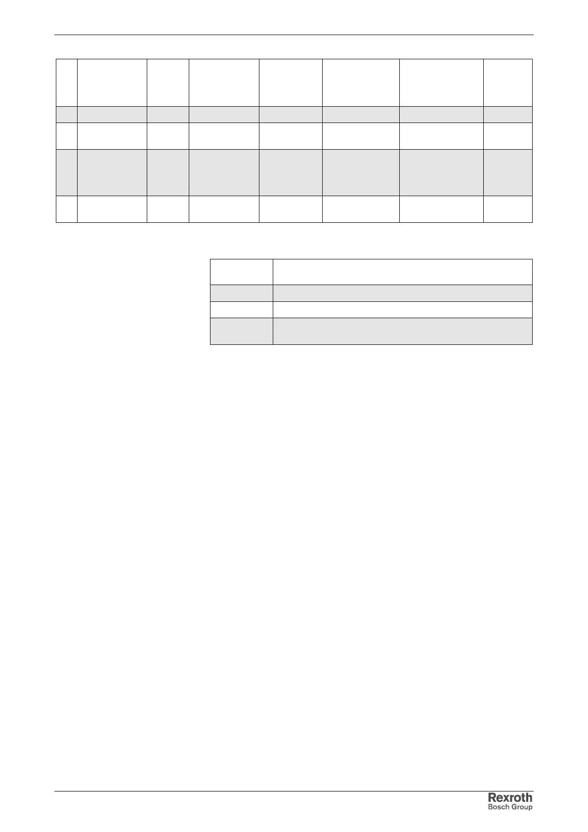
No Place of effect Pheno-
menom
Standard Conditions Coupling Test values
according
standard EN
61800-3
Perfor-
mance
level
Signal Interface Burst IEC 61000-4-4 length > 3 m clamp B
IEC 61000-4-6 length > 3 m Clamp or CDN 10 V, 0,15 – 80
MHz
B
Ports of
process;
measurement
control lines
Burst IEC 61000-4-4 length > 3 m clamp B
IEC 61000-4-6 length > 3 m Clamp or CDN 10 V, 0,15 – 80
MHz
A
Fig. 8-2: Noise immunity limit values
Evaluation
criterion
Explanation
(abbreviated form from EN 1800-3)
A Deviations within allowed range.
B Automatic recovery after interference.
C Switched off without automatic recovery.
Device remains undamaged
Fig. 8-3: Evaluation criterion
8.3 Noise Emission of Drive System
Causes of Noise Emission
Controlled variable-speed drives contain converters containing snappy
semiconductors. The advantage of modifying the speed with high
precision is achieved by means of pulse width modulation of the converter
voltage. This can generate sinusoidal currents with variable amplitude and
frequency in the motor.
The steep voltage rise, the high clock rate and the resulting harmonics
cause unwanted but physically unavoidable emission of interference
voltage and interference fields (wide band interference). The interference
mainly is asymmetric interference against ground.
The propagation of this interference strongly depends on
• configuration
• conditions of mounting
• mounting site
• radiation conditions
• wiring and installation
• of the individual drive components in the machine or installation.
If the interference gets from the device to the connected lines in unfiltered
form, these lines can radiate the interference into the air (antenna effect).
This applies to power lines, too.