1-12 Introduction Rexroth IndraDrive
DOK-INDRV*-SYSTEM*****-PR02-EN-P
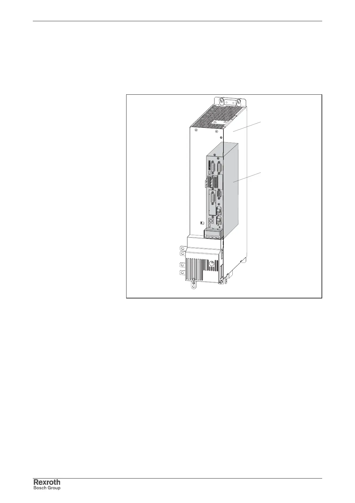
1.4 Basic Design of the Devices
Basic Design of Drive Controllers
lt_rtf2.fh7
1
2
1: power section
2: control section
Fig. 1-11: Basic design
The drive controller consists of two essential parts:
• power section
• control section
Power Section
The power section incorporates the control section and has the following
connections:
• mains voltage connection (at supply modules and HCS devices)
• motor connection (with optional motor holding brake and motor
temperature monitor)
• 24 V control voltage
• DC bus connection
• module bus connection for cross communication in the case of DC
bus connection with other devices
• connection for external braking resistor (at HCS devices)