14-38 Accessories in the Drive System Rexroth IndraDrive Rexroth IndraDrive
DOK-INDRV*-SYSTEM*****-PR02-EN-P
Mounting the HAS02 Accessories
The sheet metal of the accessories is screwed to the bottom of the drive
controller (see also figure below):
• Unscrew bottom or bottom left fixing screw of drive controller.
• Put sheet metal of accessories to bottom of drive controller and screw
down fixing screw of drive controller again.
CAUTION
Risk of damage to the drive controller caused
by too long screws!
⇒
Exclusively use screws of a maximum length of
12 mm for the thread of the shield connection XS2.
• Screw second screw (M6 x 12) in thread XS2 at bottom of drive
controller.
• Screw fixing device to sheet metal of accessories according to
desired cable routing of motor cable (45° or horizontal). (The figure
below illustrates cable routing with 45°.)
• According to diameter of motor cable, fix motor cable to
corresponding support of fixing device (12-18 mm or 19-30 mm) with
a clip. Make sure that shield of motor cable has good contact with
fixing device.
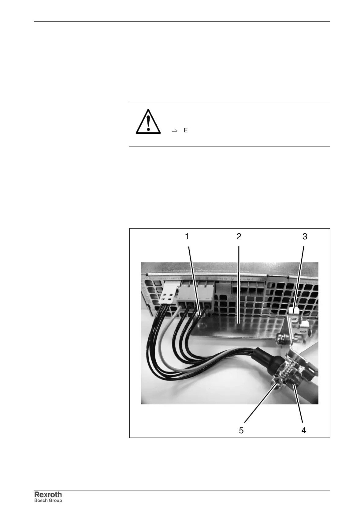
1: screw in thread XS2
2: sheet metal of accessories
3: fixing device
4: shield of motor cable
5: clip
Fig. 14-35: Shield connection of motor cable